Maker Pro
Maker Pro

High Voltage spike , disrupts Display functionality

Rohit1203

Sep 14, 2020
7
Joined
Sep 14, 2020
Messages
7
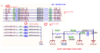
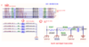
High voltage spike on 5V IO line disturbs 5.0 display functionality. all lines are protected using io buffer and SMBJ5.0A TVS, still, a high voltage spike enters the main 5V and 3.3V power lines. Spike creates spurious interrupts.

How I can stop passing high voltage spike to internal main Digital core section and save the Internal functionality and Display.
 

WHONOES

May 20, 2017
1,217
Joined
May 20, 2017
Messages
1,217
You could try a large ferrite bead on the cable.
 

Rohit1203

Sep 14, 2020
7
Joined
Sep 14, 2020
Messages
7
Thanks for the reply.
See below schematic for ESD protection and grounding connections.

As shown in the below image high voltage spike on WDATA_IN0 & IN1 line creates a spike on 5V and 3.3V Power lines and which creates issues in main processor functionality and LCD display functionality.

upload_2020-9-15_14-32-12.png
upload_2020-9-15_14-45-12.png
 

Attachments

  • upload_2020-9-15_14-29-6.png
    upload_2020-9-15_14-29-6.png
    189.7 KB · Views: 3
  • upload_2020-9-15_14-31-56.png
    upload_2020-9-15_14-31-56.png
    172.1 KB · Views: 2

Rohit1203

Sep 14, 2020
7
Joined
Sep 14, 2020
Messages
7
You could try a large ferrite bead on the cable.
Do you mean ferrite core shown in the below image on the IO cables?

51n5lh70xEL._AC_.jpg
 

Harald Kapp

Moderator
Moderator
Nov 17, 2011
13,744
Joined
Nov 17, 2011
Messages
13,744
Do I see +774 V and -871 V on the IO lines? It will be difficult (not impossible but difficult) to decouple these spikes while having a galvanic connection.
I suggest you decouple the IO lines from the µC using photocouplers (also known as optocouplers)or equivalently any form of isolated data coupler, e.g. icouplers (which is a brand name by Analog Devices, but similar componnets are available from other manufacturers, too).
 

WHONOES

May 20, 2017
1,217
Joined
May 20, 2017
Messages
1,217
I suppose the first question is... where are the spikes coming from?
 

Rohit1203

Sep 14, 2020
7
Joined
Sep 14, 2020
Messages
7
I suppose the first question is... where are the spikes coming from?
trying to simulate the field issue in the inhouse lab using an electric spark generator.
Applying spark from electric gas lighter which generates high voltage spikes on digital io lines.
 

Rohit1203

Sep 14, 2020
7
Joined
Sep 14, 2020
Messages
7
Do I see +774 V and -871 V on the IO lines? It will be difficult (not impossible but difficult) to decouple these spikes while having a galvanic connection.
I suggest you decouple the IO lines from the µC using photocouplers (also known as optocouplers)or equivalently any form of isolated data coupler, e.g. icouplers (which is a brand name by Analog Devices, but similar components are available from other manufacturers, too).

Is any way to catch the spike and discharge on earthing.
Any ready-made modules are available in the market which provides Opto isolation. now not possible to modify the board and provide the opto-isolation, but if any readyly available io isolators are available then we can use between our device and other systems.
 

Harald Kapp

Moderator
Moderator
Nov 17, 2011
13,744
Joined
Nov 17, 2011
Messages
13,744
Any ready-made modules are available in the market which provides Opto isolation
Use the search engine of your choice, look for "optoisolator module".They come in 1-channel or 4-channel flavors (that's what I've seen) from different vendors.
 

WHONOES

May 20, 2017
1,217
Joined
May 20, 2017
Messages
1,217
trying to simulate the field issue in the inhouse lab using an electric spark generator.
Applying spark from electric gas lighter which generates high voltage spikes on digital io lines.
What is your rational for testing in that manner.
 

WHONOES

May 20, 2017
1,217
Joined
May 20, 2017
Messages
1,217
So, what conditions is your device subjected to in the field? Have you taken any measurements in your device whilst operating in the field?
 

Proton

Sep 8, 2009
6
Joined
Sep 8, 2009
Messages
6
maybe, the generation of hi voltage creates a kickback voltage after discharge? in other words; collapse of the magnetic field from the secondary cuts thru the primary winding creating a backfeed which is often very high but extremely fast. Most High energy ignition systems overload my digital voltmeters, while analog meters happily read less than 12v on the primary.
a fast diode across switching transistor, perhaps would help.
digital meters in some cases get erratic within 3-4 feet implies to me that its also a very noisy enviroment
 
Top