Maker Pro
Maker Pro

Help with Voltage Transients

supermitchell2

Feb 10, 2016
8
Joined
Feb 10, 2016
Messages
8
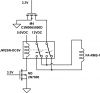
Hello, I am struggling to grasp the concept of inductance and voltage transients. Can someone please explain how these work in moderately simple terms? Ex: I do not understand things like back-EMF. If it helps, here is the circuit I am trying to build. I need to be able to calculate the transient voltages on this circuit so I can add transient voltage suppression diodes. Datasheets for the parts are included below if it helps in an explanation.
Thanks!
Note: Equations are extremely helpful if you can include them.

JW2SN-DC5V: http://www.mouser.com/ds/2/316/jw-catalog-461998.pdf

2N7000: https://www.fairchildsemi.com/datasheets/2N/2N7000.pdf

FA-RMS-15-12-X: https://www.firgelliauto.com/products/mini-rod-actuator

C3M0065090D: http://www.mouser.com/ds/2/90/3m0065090d-838565.pdf
 

Attachments

  • linear-actuator-v2.png
    linear-actuator-v2.png
    25.5 KB · Views: 115

Arouse1973

Adam
Dec 18, 2013
5,178
Joined
Dec 18, 2013
Messages
5,178
The first thing you need is a flyback diode across the relay to protect the MOSFET. When you say back EMF, where is the motor? Is it the other inductor. What voltage are you trying to limit?
Thanks
Adam
 

duke37

Jan 9, 2011
5,364
Joined
Jan 9, 2011
Messages
5,364
If you put a current through an inductance it will cause a magnetic field to be generated. This contains energy E = I*I *L/2.
When the current is reduced, this energy has to go somewhere, the inductance will try to keep the current going. If the current is switched off rapidly, very high voltages are generated across the switch, causing an arc or melting a transistor.
As Adam says, diode across the inductance will allow the current to continue until the energy is dissipated in the resistance. The diode trick can only be used if the inductance has current passes one way only. A resistor across the inductance will allow some current to pass at the expence of wasted power. With a resistor the same as the resistance of the inductor, the voltage that the switch sees will be double the supply voltage.
A zener diode can be used to limit the voltage if the current needs to be changed quickly or a capacitor in series with a resistor (known as a snubber)

In your case where the motor changes polarity, you could go for the snubber or a zener across the fet.
 

supermitchell2

Feb 10, 2016
8
Joined
Feb 10, 2016
Messages
8
If you put a current through an inductance it will cause a magnetic field to be generated. This contains energy E = I*I *L/2.
When the current is reduced, this energy has to go somewhere, the inductance will try to keep the current going. If the current is switched off rapidly, very high voltages are generated across the switch, causing an arc or melting a transistor.
As Adam says, diode across the inductance will allow the current to continue until the energy is dissipated in the resistance. The diode trick can only be used if the inductance has current passes one way only. A resistor across the inductance will allow some current to pass at the expence of wasted power. With a resistor the same as the resistance of the inductor, the voltage that the switch sees will be double the supply voltage.
A zener diode can be used to limit the voltage if the current needs to be changed quickly or a capacitor in series with a resistor (known as a snubber)

In your case where the motor changes polarity, you could go for the snubber or a zener across the fet.
Great! Thanks for the help! Just want to check, is I*I = I^2? Also, when I have found E, how do I calculate the time it takes for this energy to dissipate through the circuit and the voltage of the transient? I need to know because I don't know how to pick the correct part number to do the job.
 

(*steve*)

¡sǝpodᴉʇuɐ ǝɥʇ ɹɐǝɥd
Moderator
Jan 21, 2010
25,510
Joined
Jan 21, 2010
Messages
25,510
Yes I*I = I^2.

A diode across an inductive load needs to have a voltage rating of at least the supply rating (the voltage across the inductive load) and requires to have a peak current capacity at least as large as the current through the inductive load.
 

duke37

Jan 9, 2011
5,364
Joined
Jan 9, 2011
Messages
5,364
When I first used a computer I was castigated (very painful) for using A^2 since it involved taking logarithms, mutiplying by 2 and then taking antilogarithms so wasted CPU time. A simple multiplication was much faster.

The time constant of the decay will be L/R, A relay will hold in to quite low currents so might manage a couple of time constants. Relays also take time to switch over. Fast relays can go to 100Hz or so.
I have been playing with a mechanical counter to count shaft rotations and will use a zener diode to make it switch quickly.

In your circuit, nothing seems to want high speed control. Any relay is likely to switch in less than a second.
What parts do you want to specify?
 

supermitchell2

Feb 10, 2016
8
Joined
Feb 10, 2016
Messages
8
When I first used a computer I was castigated (very painful) for using A^2 since it involved taking logarithms, mutiplying by 2 and then taking antilogarithms so wasted CPU time. A simple multiplication was much faster.

The time constant of the decay will be L/R, A relay will hold in to quite low currents so might manage a couple of time constants. Relays also take time to switch over. Fast relays can go to 100Hz or so.
I have been playing with a mechanical counter to count shaft rotations and will use a zener diode to make it switch quickly.

In your circuit, nothing seems to want high speed control. Any relay is likely to switch in less than a second.
What parts do you want to specify?
I just wanted to make sure that there would be no issues with the inductor discharge rate. After hearing what you wrote, I no longer have any worries about it. My maximum relay speed will be once every 10 seconds or so, probably a lot less than that on average. Thanks for the help with the time constant thing though, I read an article the other day that mentioned that and its nice to see it from someone else.
 

supermitchell2

Feb 10, 2016
8
Joined
Feb 10, 2016
Messages
8
Hello, I was told by an electrician friend today that something like this may work for my purposes. This would be far more useful for me because I do not currently own any diodes. Would something like this work? (values are not included, its just a thought)
 

Attachments

  • Inductor.png
    Inductor.png
    10.5 KB · Views: 46

(*steve*)

¡sǝpodᴉʇuɐ ǝɥʇ ɹɐǝɥd
Moderator
Jan 21, 2010
25,510
Joined
Jan 21, 2010
Messages
25,510
A resistor could be used but it will waste power when the relay is on. The resistor needs to be chosen so that the voltage across it is compatible with the ratings of the mosfet.
 

hevans1944

Hop - AC8NS
Jun 21, 2012
4,880
Joined
Jun 21, 2012
Messages
4,880
This works, but at the expense of extra power dissipation in the resistor while the relay coil is energized. See @duke37's post #2.
 
Top