Adam monkhouse
- Aug 18, 2016
- 3
- Joined
- Aug 18, 2016
- Messages
- 3
Hello,
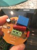
I'm In need of some help please. I bought a 230v pir from the Internet as I had seen a thread on how to change it to operate at 24vdc. Once mine arrived and I took it apart it was slightly different than the one in the blog which I had seen which made it difficult to follow. Spent the last 3 hours trying to figure it out but have become stuck.
I wish to supply the unit with 24vdc and get a switched 24vdc back when the PIR operates. I know I have to put in a couple of links in place of the components Iv removed but not sure where.?
Do I need to leave the signal diodes in and also what about the resister near the switched live?
Any help would be greatly appreciated
Thanks
Adam