Situation:
I have a 3D projector that has an output jack for external transmitter. The external transmitter needs ~+5v signal that pulses from 0v to 5v ( +1v->+3v seems to trigger it) to keep the glasses in sync with the PJ. The PJ is only outputting a 0-1v signal.
I've built a simple op amp (from someone else's design) that uses a 5v usb power supply and is suppose to take the signal coming from PJ and send ~5v signal to the external transmitter when the out jack is at 1v.
Problem:
First I'm a complete noob to electronics. Second the op amp I built works to amplify the signal and trigger the external emitter. It generates a 0.7v->3.5v signal. I tested this on my bread board and it worked with the PJ. I then built a box with a cable coming in from the PJ and out the transmitter. This is where things went wrong. The op amp is too sensitive. If I touch the op amp input cable with my hand static from my hand triggers the op amp.
Question:
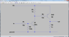
How do I fix the below diagram to make it less sensitive but still trigger quickly on the 1v signal form the PJ or is there a better design I should use?:

thanks, Jeff
I have a 3D projector that has an output jack for external transmitter. The external transmitter needs ~+5v signal that pulses from 0v to 5v ( +1v->+3v seems to trigger it) to keep the glasses in sync with the PJ. The PJ is only outputting a 0-1v signal.
I've built a simple op amp (from someone else's design) that uses a 5v usb power supply and is suppose to take the signal coming from PJ and send ~5v signal to the external transmitter when the out jack is at 1v.
Problem:
First I'm a complete noob to electronics. Second the op amp I built works to amplify the signal and trigger the external emitter. It generates a 0.7v->3.5v signal. I tested this on my bread board and it worked with the PJ. I then built a box with a cable coming in from the PJ and out the transmitter. This is where things went wrong. The op amp is too sensitive. If I touch the op amp input cable with my hand static from my hand triggers the op amp.
Question:
How do I fix the below diagram to make it less sensitive but still trigger quickly on the 1v signal form the PJ or is there a better design I should use?:
thanks, Jeff