Maker Pro
Maker Pro

Help With Kids Homework

Rob1901

Jul 27, 2015
1
Joined
Jul 27, 2015
Messages
1
This section is on fundamentals of magnetism.

The question is List at least 3 things you could do to the circuit on the left to create a current in the wire loop without connecting them physically.

My son has come up with:

Closing the switch so the power will go through the circuit
The other is moving the circuit closer to the wire loop

I have no idea on this stuff so any help would be great. I have attached the diagram.
Thanks in advance.
 

Attachments

  • electro.jpg
    electro.jpg
    18.1 KB · Views: 163

Laplace

Apr 4, 2010
1,252
Joined
Apr 4, 2010
Messages
1,252
In the general case there are only three actions that will induce a voltage in the wire loop.

A. Increasing the magnitude of the current flowing in the circuit 'coil'.

B. Decreasing the magnitude of the current flowing in the circuit 'coil'.

C. Moving the circuit coil so static field lines generated by the flowing current cut through the wire loop.

That's all there is, although I wonder about the relativistic effects of massive acceleration of the setup to near light speed.
 

pgib8

Jul 26, 2015
107
Joined
Jul 26, 2015
Messages
107
I'm sorry but this is a really bad assignment (my opinion). I'm totally struggling with it, trying to figure out what the teacher wants (lol).
 

Gryd3

Jun 25, 2014
4,098
Joined
Jun 25, 2014
Messages
4,098
I'm sorry but this is a really bad assignment (my opinion). I'm totally struggling with it, trying to figure out what the teacher wants (lol).
I agree with you, based on what was provided... but I was not in class, so it's hard to tell.

Some details for you that may greatly help:

Flowing Electricity will create a Magnetic Field around the wire. The 'Right Hand Rule' will give you more detail about the direction of this field in relation to the direction of the Electrical current.
This is a two way relationship though... which means that a Magnetic Field can actually 'create' Electrical Current as well!
There is a catch though. The Magnetic Field itself isn't exactly what creates the current... it's the 'change' in the Magnetic Field that does.

There are two ways to change the Strength of the magnetic Field:
- Physically move toward or away from the Field. (Used in Generators)
- Change the Electrical Current that is causing the field. (Used in Transformers)

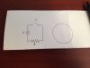
Is the paper provided, there is no current flow because the switch is open. As soon as you close the switch, current will flow which will create a new magnetic field around the wire in the circuit. If the loop on the right is close enough, the change of magnetic field in the wire of the circuit will cause a briefly cause current to flow in the loop. When you open the switch, the magnetic field around the wire of the circuit changes again... which will cause current to flow in the opposite direction in the loop if it's close enough.
Additionally, you can leave the switch closed, and move the loop toward and away from the circuit which will cause brief Electrical alternating current in the loop.

Hopefully this helps you out. If you want to try a simple experiment to show off the electrical creation of Magnetism, you can make an electro-magnet with a nail, some wire and a battery ;)
Tightly and neatly wrap the wire around the length of the nail, and apply voltage to the wire. The magnetic field around the wire will create a temporary magnet with the nail that you can use to pick up small items like paper-clips and loose change. You can also repel or attract other magnets based on the polarity of the battery! Does it push a magnet away, reverse the battery and try again.
 

Harald Kapp

Moderator
Moderator
Nov 17, 2011
13,722
Joined
Nov 17, 2011
Messages
13,722
Changing the voltage of the battery, replaciing the battery by an AC source or changing the resistance are other options, although it isn't explicitly indicated that these options are allowed "things you could do to the circuit".
 

Laplace

Apr 4, 2010
1,252
Joined
Apr 4, 2010
Messages
1,252
I would agree with these two answers:

Closing the switch so the power will go through the circuit
The other is moving the circuit closer to the wire loop


What the teacher wants is for you to recognize what will induce a current to flow in the wire loop. In the general case, current in the loop is caused by a change in the magnetic field intersecting the loop. Increasing field strength causes current to flow in one direction; decreasing field strength causes current to flow in the other direction.

Closing the switch will increase the field strength at the loop. During the relatively short time period that circuit current is increasing, current also flows in the loop.

Moving the circuit will also change the field strength at the wire loop, causing current to flow in the loop during the period of movement.

What third thing could you do in the circuit that would cause a change in the circuit current?
 

Colin Mitchell

Aug 31, 2014
1,416
Joined
Aug 31, 2014
Messages
1,416
You really have to convert the symbols to real components and then thread the loop into the circuit so that it hangs on the wire making the connection between the switch and the resistor.
Current will only really flow in the loop when the wire is inside the loop.
 

Gryd3

Jun 25, 2014
4,098
Joined
Jun 25, 2014
Messages
4,098
You really have to convert the symbols to real components and then thread the loop into the circuit so that it hangs on the wire making the connection between the switch and the resistor.
Current will only really flow in the loop when the wire is inside the loop.
... I hope you are kidding, and if not, can you please clarify, because orientation of the loop with respect to the circuit is very important.

Two parallel wires allow for this behaviour. Two wires intersecting at 90 degrees do not.
Placing the loop on a wire of the circuit so that the wire is a tangent or secant to the loop will induce current in the loop.
Placing the loop on the wire of the circuit so that the wire spans the diameter of the loop will not result in current flow.** Stringing the circuit 'through' the loop will not induce current wither unless the tangent or secant layout is followed.

2000px-CIRCLE_LINES.svg.png

**Note that if the magnetic field is strong enough, it will induce currents in the loop but, the currents will cancel each other out!
If you split the circle in half with the wire from circuit, then a current will be induced in one half going clockwise, and the other half would be counter-clockwise. (Both currents would flow toward the same end of the circle... cancelling each other out)
 

Colin Mitchell

Aug 31, 2014
1,416
Joined
Aug 31, 2014
Messages
1,416
What you are saying, in fact, is entirely incorrect.
Look at a clamp-on AMMETER.
It has to be around the wire to detect the current-flow.
You are confusing two different features of INDUCTION.
Yes, two parallel wires can be used to show that the second wire picks up the field from the first.
But over a short length, the effect is microscopic.
When you place a ring of wire around a conductor you are actually creating the TRANSFORMER EFFECT with the secondary being a single SHORTED TURN.
We know that a shorted turn "draws" "removes" "sucks" the greatest current from a transformer and it also has the greatest effect when the current is rising and falling in a single wire.
The current-carrying wire INDUCES a current in the shorted turn.
 

Gryd3

Jun 25, 2014
4,098
Joined
Jun 25, 2014
Messages
4,098
What you are saying, in fact, is entirely incorrect.
Look at a clamp-on AMMETER.
It has to be around the wire to detect the current-flow.
You are confusing two different features of INDUCTION.
Yes, two parallel wires can be used to show that the second wire picks up the field from the first.
But over a short length, the effect is microscopic.
When you place a ring of wire around a conductor you are actually creating the TRANSFORMER EFFECT with the secondary being a single SHORTED TURN.
We know that a shorted turn "draws" "removes" "sucks" the greatest current from a transformer and it also has the greatest effect when the current is rising and falling in a single wire.
The current-carrying wire INDUCES a current in the shorted turn.
.. Colin. Those meters use a split core transformer with multiple turns of wire around the 'core' ... You will notice that those clamp on meters 'cant' have multiple coils of wire because the clamp needs an open end in order to be fastened to a wire to test.

If you zigzag the wire back and forth in the clamp... you end up with a 'net' induced current of 0, as half the winding is in the opposite direction compared the the first.

If you put that loop of wire in the ops homework around a 'wire-wound' resistor, you would get current flow...

As far as transformers are concerned.. they use one or more turns of wire.
The magnetic field must have a perpendicular element to the wire in order to induce any current. If you wrap wire around a plastic tube, and pass a wire down the middle, the wire down the middle will be parallel to the magnetic field and no current will be induced. (Except perhaps a very minute amount caused by the pitch that you happen to wrap the wire on the tube at. This would be a helix though...)

If you can provide any documentation or links that back your post, please share and I'll back off.
 

Colin Mitchell

Aug 31, 2014
1,416
Joined
Aug 31, 2014
Messages
1,416
The fact that you are missing out on is the clamp-on meter is a SINGLE TURN. This single turn is now used as the primary of a transformer that steps up the voltage to operate detecting components.
Many of these meters simply use the magnetic flux produced in a core to activate a HALL DEVICE.
However the fact is this: You are going to get a much greater reading or much greater effect if you place the shorted turn over the wire carrying the current and have the wire passing through the centre of the shorted turn. This requires a 3D circuit.
 

Gryd3

Jun 25, 2014
4,098
Joined
Jun 25, 2014
Messages
4,098
The fact that you are missing out on is the clamp-on meter is a SINGLE TURN. This single turn is now used as the primary of a transformer that steps up the voltage to operate detecting components.
Many of these meters simply use the magnetic flux produced in a core to activate a HALL DEVICE.
However the fact is this: You are going to get a much greater reading or much greater effect if you place the shorted turn over the wire carrying the current and have the wire passing through the centre of the shorted turn. This requires a 3D circuit.
Clamp on meter commonly uses a split core. The number of turns directly relates to the output voltage from the device.
The meters that use hall sensors don't use a loop of wire... but a split ferrite core (or similar) and place a small hall effect sensor in an air gap of the split core.

I've been referring to the right-hand rule which describes the relation between force, magnetic field, and motion of electrons. This is very basic high-school physics topic.
Again, can you please share anything other than how a subset of clam-meters 'might' work?

https://en.wikipedia.org/wiki/Right-hand_rule
 

Colin Mitchell

Aug 31, 2014
1,416
Joined
Aug 31, 2014
Messages
1,416
The reason why clamp meters use a Hall effect device is this: So they can measure DC.

You are confusing the issue with irrelevancies.
"Clamp on meters commonly uses a split core" They use a split core so the meter can be wrapped around a wire.
 

Gryd3

Jun 25, 2014
4,098
Joined
Jun 25, 2014
Messages
4,098
The reason why clamp meters use a Hall effect device is this: So they can measure DC.

You are confusing the issue with irrelevancies.
"Clamp on meters commonly uses a split core" They use a split core so the meter can be wrapped around a wire.
That's what I have been saying the entire time!

You can't put a loop of wire around a straight wire and have an induced current.
Your reason for 'yes you can' was using an example of a current clamp meter out there. You also brought up the hall sensor.

My counter to that is that a current clamp meter is NOT a loop of wire around the wire you are testing, but is most often a split core transformer with at least one loop of wire wrapped around the core to take measurements.
Your description of the transformer effect is flawed. The requirement for this is two parallel conducting wires, or some form of passing magnetic flux through the the wire at a right angle. Transformers do this by using two coils either stacked on each other, or coupled with a core of some sort.
 

Colin Mitchell

Aug 31, 2014
1,416
Joined
Aug 31, 2014
Messages
1,416
I have told you before, that you are entirely WRONG.
The first current metes used 10 turns or more of wire on a coil and this coil was placed over the wire to detect the current.
But this is very inconvenient when the wire is already connected to the switchboard etc.
So, some clever person produced a single turn that joined at the top to make a SHORTED TURN.
When a core is used, it is not a split core but simply a core that OPENS UP.
It does not have an air gap and a number of turns are wound on the core.
The wire passing through the core is simply a primary winding consisting of a single turn.
But, unfortunately we don't have a luxury of being able to wrap the primary in a complete circle to prove it is a single turn.
The manufacturers of the clamp meter realize this and have made the sensitivity of the pick-up more sensitive to adjust for the fact that the primary winding is not a full turn.
 

Gryd3

Jun 25, 2014
4,098
Joined
Jun 25, 2014
Messages
4,098
I've drawn a picture to describe what I am trying to explain.
The red wire is the wire carrying current. In this example, this is AC.
If the blue item were a wire, there would be NO current. There would however be a varying magnetic field that would be
concentrated in the blue item if it were a core, such as those used in clamp on ammeters.
The Green coil on the core is where the current is induced. You might notice that the green coil, if reduced to a single loop, would physically be running parallel to the red wire.
In the case of the DC ammeters you brought up, the blue core has a small air gap in which a hall sensor is placed.
Untitled.jpg

How else can I explain the right hand rule and physics?

Do you have any documents, or articles that you can reference, or will you continue calling me wrong while only providing your opinions and thoughts on the matter.
Perhaps I am not interpreting the right hand rule properly?
Use something other than 'your wrong' and 'ammeters use a single loop of wire' to make your point.
 

Colin Mitchell

Aug 31, 2014
1,416
Joined
Aug 31, 2014
Messages
1,416
You have answered your own question.
There is current flowing in the blue loop and this becomes the primary winding of a transformer between the blue and green windings.
The green winding simply increases the voltage.

If the blue item were a wire, there would be NO current.
What do you think a ferrite core is?????
It is a thick wire with very low resistance.
Ferrite has the same letters as IRON Fe. Ferrite material can be replaced with iron and iron can be replaced with copper and everything will work exactly the same. The only difference is the efficiency.
 

duke37

Jan 9, 2011
5,364
Joined
Jan 9, 2011
Messages
5,364
I agree with Gryd3
'Ferrite' can have different meanings. It is the low temperature body centred cubic magnetic phase of iron. This is used in transformer cores and is split into laminations to increase resistance and reduce eddy currents. It is also alloyed with 4% silicon to increase resistance. Current in the core is NOT wanted, a copper core would not work and the eddy currents would give large losses.

'Ferrite' is also used to decribe magnetic compounds of iron and other elements in a spinel crystal structure.
Two common types are manganese zinc and nickel zinc. The magnetic properties and the resistance will depend on the type. It is better to have a high resistance to reduce eddy currents. Try to measure the resistance of a ferrite aerial rod (loop stick), the resistance will be very high.

I refer you to "Soft Ferrites properties and applications" by E.C. Snelling
 
Top