Maker Pro
Maker Pro

Help with Atmega328 project

fastpcuser

Apr 8, 2012
31
Joined
Apr 8, 2012
Messages
31
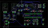
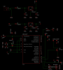
I'm trying to build a circuit that uses two switches to turn on and off pump. I had it all set up on breadboard and it works fine, but when I created PCB it is not working properly. The pump does not turn on only when I unplug the power and plug it back in. I'm using 12V 1200mA power supply with LM7812C regulator for the pump and LM7805 for the Atmega328P microcontroller. This Microcontroller has the Optibot loader from Arduino. I tried to test with with the simple led blink test, and all my LED would blink the way they should. but I can't seem to get the motor/pump turn on.

I have attached PCB drawing ( need to clean it up little) and schematics.

PS: I'm new to electronics. Be nice.
 

Attachments

  • Circuit.png
    Circuit.png
    49.9 KB · Views: 3,050
  • schem.png
    schem.png
    52.8 KB · Views: 487

CocaCola

Apr 7, 2012
3,635
Joined
Apr 7, 2012
Messages
3,635
The pump does not turn on only when I unplug the power and plug it back in

Clarify this, it works sometimes? But, then fails to work, and a reboot fixes it? That suggest a problem with your code...

Also you need a resistor on the base of the transistor, so you don't kill it, and you also have a problem with the voltage levels... You are using a 12v supply and trying to regulate it to 12v with an LM7812C... Either bypass the LM7812C and use the already existing 12 volts, or up your supply voltage in excess of 14.6v as the LM7812C needs at least 14.6v to operate properly...
 

fastpcuser

Apr 8, 2012
31
Joined
Apr 8, 2012
Messages
31
Actually the PS is 12 but the output is 14.6v . The motor turns on for few seconds after the microcontroller resets other than that it doesn't do anything.
 

CocaCola

Apr 7, 2012
3,635
Joined
Apr 7, 2012
Messages
3,635
Actually the PS is 12 but the output is 14.6v . The motor turns on for few seconds after the microcontroller resets other than that it doesn't do anything.

It's either a 12 volt power supply or a 14.6 volt one, at what load did you measure the 14.6 volts? I suspect that is the the no load voltage on the '12 volt' power supply, and I'll bet as the load increases the voltage drops quite rapidly... When it drops bellow 14.6 volts the LM7812C no longer performs properly, and that means it is not properly supplying the motor a that point... You need in excess of 14.6 volts to properly run the LM7812C, try an 18-24 volt supply and see how that works, or as I said skip the LM7812C and run the motor directly from your existing power supply...
 

fastpcuser

Apr 8, 2012
31
Joined
Apr 8, 2012
Messages
31
just got home from work so .... the PS without any load is 15.78V Dc (measured with multimeter.). I think I have found one error ..... my button/switch is missing pulldown resistor. Also is there any other (better) transistor that I can use than TIP120 ? I'm going try adding that resistor to see if it will do anything.
 

CocaCola

Apr 7, 2012
3,635
Joined
Apr 7, 2012
Messages
3,635
just got home from work so .... the PS without any load is 15.78V Dc (measured with multimeter.).

So now it's went from a 12v supply to a 14.6v supply to a 15.78v supply? Ever changing values isn't productive to solving a problem...

And you go through a rectifying diode that skims off about 0.7 more volts leaving you at about 15v max... If that power supply drops even half a volt under load you are bellow what the LM7812C wants and could still very well be the source of your problem...

Also is there any other (better) transistor that I can use than TIP120 ?

Your choice of transistor is not the problem...

Without the code and intended function of the circuit trying to troubleshoot beyond what I have suggested already is really just a shot in the dark...

You seem to continue to be very hesitant to heed my advice on the power supply, taking an argumentative stand when you are attempting to eliminate possible issues isn't beneficial to narrowing down the cause of the problem...

I also have to asked why on earth are you using a micro if the intended purpose is just to use switches to turn on/off a pump? Seems like excessive overkill...
 
Last edited:

(*steve*)

¡sǝpodᴉʇuɐ ǝɥʇ ɹɐǝɥd
Moderator
Jan 21, 2010
25,510
Joined
Jan 21, 2010
Messages
25,510
It might be useful to measure the output of the 5V regulator and also to see how you're driving that transistor.

We will need at least a partial circuit diagram.

Is the pump on or off when you're taking your measurements?

Have you tested the circuit using a different load (for example just a LED)?
 

BobK

Jan 5, 2010
7,682
Joined
Jan 5, 2010
Messages
7,682
You TIP120 is probably losing you 2V. Maybe you would be better off to use the 14V input rather than regulating it down to 12V. A MOSFET would have been a better choice.

Bob
 
Top