I think that's doable with a fairly simple circuit.
Fortunately the current is low, so dissipation will likewise be low.
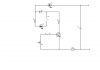
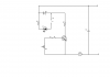
This requires 2 transistors, both can be the 2N3904 that you mentioned.
The way this works is that R1 turns on Q1 to allow current to flow through your load. Normally nothing would limit this current, but in this case, when the current through R2 + R3 increases enough to turn on Q2, Q2 prevents it from rising any higher.
This circuit is not perfect, but it should work over the fairly small 10:1 range you're interested in.
How to determine the component values:
1) R1 should pass about 2% of the maximum current required at the minimum input voltage less 1.4V. Let's assume that the input voltage ranges between 12V and 14V, and the max current is 2mA. Therefore the required resistance is ((12 - 1.4)/0.002) * 0.02 = 265000 ohms. A 220k resistor would be fine.
2) R2 should drop 0.6V at the maximum current. So at 2mA, R2 = 0.6/0.002 = 300 ohms. 270 ohms would be a good choice.
3) R3 should be chosen so that the voltage dropped across R2 and R3 at the minimum current is 0.7V. So R3 + R2 = 0.7/0.0001 = 7000 ohms. Thus R3 should be 7000 - 470 = 6530 ohms. The closest you're likely to come is 10k. R3 is this a 10k potentiometer.
You may note that I used 2% in step 1. I am assuming the transistor has a gain of at least 100, and that we'll have a base current twice that (so we ensure there is regulation happening). The 2N3904 specifies a minimum gain of 70 at 1mA, so we're in the ballpark.
In part (2) I use 0.6V, while in part (3) I use 0.7V -- why? Well the voltage required to turn Q2 on is typically between 0.6V and 0.7V. I use the one which tends to cause errors to widen the range of currents.
Because the current is so low, we can pass all of it through a potentiometer. You COULD NOT just change resistance values in this circuit to get currents from 100mA to 1A. The current through the potentiometer would require either an expensive potentiometer or would make it emit smoke.
Now we have the values, let's calculate how this will perform.
The constant current source will require about 1.7V to operate. Thus the maximum voltage available to the load will be about 10.3V (that's at the minimum input voltage).
At 2mA, this allows for a resistance of up to 5k ohms. At 0.1mA the maximum resistance would be about 100k ohms.
If you had a load which exhibited a higher resistance, the current would fall. You could counter this by using a higher input voltage. With the transistors chosen, the maximum input voltage would be about 40V.
The current will change slightly with the input voltage, load, and temperature, but the variation will be quite small.
")
