Maker Pro
Maker Pro

Help the Noob, identify missing parts on simple circuit.

axel.sandi

Sep 18, 2016
3
Joined
Sep 18, 2016
Messages
3
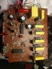
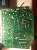
well i have this old 3 bulb light organ and i decided to add 3 additional bulbs since the circuit has the ability to power 6 bulbs. i have added the parts that seemed obvious to me but i need an expert or someone with knowledge to tell me what parts i still need to add and where. this is my first project i am learning but still a noob! thank you very much in advance and keep up the solid work!!! axel.
 

Attachments

  • IMG_20160919_003304.jpg
    IMG_20160919_003304.jpg
    279.8 KB · Views: 131
  • IMG_20160919_003201.jpg
    IMG_20160919_003201.jpg
    267.8 KB · Views: 106

grumps

Jul 11, 2015
12
Joined
Jul 11, 2015
Messages
12
scan and print foil side ( without color ) then hand - draw components , over print out :

relist result with available voltages so we can guess how each ' bulb ' is meant to work ;
 

axel.sandi

Sep 18, 2016
3
Joined
Sep 18, 2016
Messages
3
t
scan and print foil side ( without color ) then hand - draw components , over print out :

relist result with available voltages so we can guess how each ' bulb ' is meant to work ;
thank you very much!! its my first time doing such things so... excuse my stupidity. What i can tell now is that its 230V 50Hz and the three original bulbs are 40W. It has a music sensor (mic) and an adjuster for speed and one for sound sensibility
 

73's de Edd

Aug 21, 2015
3,628
Joined
Aug 21, 2015
Messages
3,628
axel sandi. . . . . . .

As requested . . . . here is the mark-up of where all of the "lite bubs" (lamps) go into the unit.
Their one shared connection, is a commuon buss a l l l l l l l along the edge of the PCB.
If you just have ONE lamp . . . . move it between positions to test out all sections.

If further analysis . . . .due to a non working unit . . . . is needed.
Give the numbers of IC1 and 2 as well as the Q3-Q7 Lamp driver Triac's.
And is LARGE yellow rectangle . . .a BIG poly cap ? and give its marked capacitance and voltage rating.
Noticed that they made a change on a few of the R/C snubbers . . . . in the use of some 27 ohm
2 watt units . . . . just bet that they ran out of stock ! ( No . . it was you.)
The pcb part spacing layout was made for a 1 watt unit and that rating was being totally adequate.

COMPONENTS + Partial DUAL LAYOUT + FOIL PATTERN :
VpIjtcx.jpg


FEEDBACK ON BOARD PARTS:

U1 . . . . . . . . . . . . . . . . . . . CD4093BF Quad 2-input NAND w/Schmitt Triggers
U2 . . . . . . . . . . . . . . . . . . . CD4017CE Decade Counter/Divider w/ 10 Decoded Outputs
Largest YELLOW Poly cap 0.68ufd -280V
Largest RED Mylar cap . . 0.47 ufd -400V
Q3-7 Triac's . . . . . . . . . . BT134A Logic level Triacs . . .T1 . . .T2 . . .G

" for sound sensibility . . . . . . . ( sensitivity ) "


upload_2016-9-21_3-3-30.png


73's de Edd
 
Last edited:

axel.sandi

Sep 18, 2016
3
Joined
Sep 18, 2016
Messages
3
Hello 73's de Edd !

thank you so so much for your help so far.

U1 is 49DV9HK CD4093BE and U2 is 59C3JJM CD4017GE. on the large yellow rectangle is written: MEX-X2 MKP 0.68mF -40/85/21 280V EN132400. the big red one: CBB22 474J400V
Q3-7: PJ 600G BT134 A1106 B1 (Q3-5 as well as R11-15 and C12-14 i put in myself to have the additional 3 bulbs working. but yet i dont know what other parts are missing for them to run)

thank you very very much!

axel.
axel sandi. . . . . . .

As requested . . . . here is the mark-up of where all of the "lite bubs" (lamps) go into the unit.
Their one shared connection, is a commuon buss a l l l l l l l along the edge of the PCB.
If you just have ONE lamp . . . . move it between positions to test out all sections.

If further analysis . . . .due to a non working unit . . . . is needed.
Give the numbers of IC1 and 2 as well as the Q3-Q7 Lamp driver SCR's.
And is LARGE yellow rectangle . . .a BIG poly cap ? and give its marked capacitance and voltage rating.
Noticed that they made a change on a few of the R/C snubbers . . . . in the use of some 27 ohm
2 watt units . . . . just bet that they ran out of stock !
The pcb part spacing layout was made for a 1 watt unit and that rating was being totally adequate.

FOIL-COMPONENTS + Partial DUAL LAYOUT :
VpIjtcx.jpg


73's de Edd
 
Last edited by a moderator:
Top