Although I am nowhere near the electronics genius' as the other repliers to your post are, I DO have experience with screwing up traces with a soldering iron, so I will explain how to fix the problem you have now. The other guys are great at telling you what you have and what you have done, just not so good, in this case, at telling you how to fix the problem. Not a dig on them, they just need to realize they are not talking to electronics whiz's like themselves.
So here is what you need to do: First, find out just exactly where each pin on that USB port goes to after it leaves that port. I see four pins on the back side of the port. They have to go somewhere. The port itself should have solder points on the four corners of the port. The solder points on the four corners usually go to ground. You may have to look at the other side of the circuit board to tell, or you may have to magnify (with a magnifying glass) the traces (the electrical paths) on the top of the board and follow them to their next point. Since it appears some of your solder points may be ok, follow the traces for all of them and ensure, with something that will measure continuity (a DVM), that you have continuity between the pin of the USB port and the next place the trace from that pin goes to. More than likely, that second pin will not show conductivity.
Hopefully you have not destroyed the traces with too much heat from your soldering iron and you will be able to still see and follow the traces. If not, then you will need a schematic of the board. If you find one or more that will not complete the path from the USB port to the next point through a re-soldering (be very careful with the heat), then the fix is to get a short piece of thin (higher numbered gauge) insulated wire. You can use non-insulated wire as long as it retains its shape if bent. Take that wire and carefully solder one end to the pin on the USB port and then solder the other end of the wire to the next place the trace would go to from that pin. You have to be very careful not to bridge (connect with solder) any of the solder points you make next to any of the other components. Also, if you are using non-insulated wire, make sure the wire only contacts the USB pin and the next place the path goes to and make sure it cannot accidentally come in contact with anything else on the board other than the intended next place. After soldering on the wire, test again for continuity from the USB port pin to the next point in the path to make sure the circuit is complete there.
As advised before, the USB port has to be secured to the board. Some of those USB ports have pins that actually extend through the board to secure them to the board with solder. Glue is also used. A common failure is what you have experienced, in that the port has separated from the board, lost its soldered electrical connections, and has resulted in the malfunction you have to repair. Had it been secured properly, this may not have happened. However, you did advise that this port is the most often used port on the board, so it is moved quite a bit.
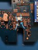
I have attached a pic of a board where a component had fried and ruined the surrounding area of the board. Jumper wires (between the arrows) were soldered in to complete the circuit, because the traces were burned away. This repair was made with hard, non-insulated wire, but it shows what I have explained above.
One other thing I noticed while looking at your pictures. Take a close look at the pins coming from the back side of the board through the top. There are 8 of them near the Mic input. Some of the pins appears as if they have been cold soldered and may need to be fixed.
Be careful. Take your time. Let us know if you are able to fix it, and good luck.
")