Maker Pro
Maker Pro

Help! Reading Voltage with Arduino

Ali Kazemian

Oct 12, 2015
8
Joined
Oct 12, 2015
Messages
8
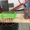
I'm trying to build a device which measures the electrical resistivity of a paste (cementitious materials) using Arduino. Four steel probes are put inside the paste (jumper wires attached to them). Two outer probes apply AC signals (Square signals- Frequency 1 kHz- Voltage(peak to peak)= 14 V) and two inner probes should measure the potential difference. Then the resistivity could be calculated by a formula. Schematic and sample pictures are attached.
I managed to apply the desired AC current, but the issue that I have is about reading the potential difference (two inner probes) by Arduino. When I used a multimeter (set to AC mode) I read some values (voltage) which should be correct, but using Arduino as the same time I read different values! I cannot see why!
I use analogue pin (A0) to read values, convert it to voltage ( float voltage = sensorValue * (5.0 / 1023.0); ) and print it to serial monitor. I programmed Arduino to read values 10 times during a second and report the maximum value only (although since symmetric square waves are applied, only direction of current should change, not the amount). There is not a linear relationship between values either (Examples: (Multimeter: 0.712 V, Arduino: 1.15 V)-(Multimeter: 0.68V, Arduino: 1.10V)-(Multimeter: 0.67V, Arduino: 1.03V)).
I would really appreciate any help from you guys!
 

Attachments

  • IMG_2119.JPG
    IMG_2119.JPG
    225.7 KB · Views: 94
  • Photo Nov 02, 2 58 30 PM.jpg
    Photo Nov 02, 2 58 30 PM.jpg
    353.8 KB · Views: 114
  • scheme.jpg
    scheme.jpg
    33.9 KB · Views: 123

dorke

Jun 20, 2015
2,342
Joined
Jun 20, 2015
Messages
2,342
You have a few problems here they are related to
the AM-510 multimeter:

1.You are using a square wave, since your DMM isn't a true RMS one you are getting an error in the reading.
2.The signal you are using is 1Khz which is higher than the max frequency of 400Hz your DMM can handle.

To remedy this problem Use a Sine-Wave of Less than 400Hz.
and make the Aurdiono calculations according to this.

Better yet,
If possible, Use DC instead,makes life a lot easier.
 

Ali Kazemian

Oct 12, 2015
8
Joined
Oct 12, 2015
Messages
8
You have a few problems here they are related to
the AM-510 multimeter:

1.You are using a square wave, since your DMM isn't a true RMS one you are getting an error in the reading.
2.The signal you are using is 1Khz which is higher than the max frequency of 400Hz your DMM can handle.

To remedy this problem Use a Sine-Wave of Less than 400Hz.
and make the Aurdiono calculations according to this.

Better yet,
If possible, Use DC instead,makes life a lot easier.

Thanks for the response. You mean the values shown by multimeter are wrong and the ones reported by the Arduino are correct? AM-510 specs says it can handle signal frequencies of 10Hz-10MHz. Unfortunately I cannot change the frequency of signals nor change AC to DC, since they are standard test procedure.
 

dorke

Jun 20, 2015
2,342
Joined
Jun 20, 2015
Messages
2,342
Well,
Yes the DMM measurement is not correct for sure!
It is 10Hz to 10Mhz range in frequency measurement only.
but in ACV only 45Hz to 400Hz !

Use a SCOPE or If your lab has any true RMS DMM use it.
The AM-510 is not good for taking this measurement!
 

Ali Kazemian

Oct 12, 2015
8
Joined
Oct 12, 2015
Messages
8
Well,
Yes the DMM measurement is not correct for sure!
It is 10Hz to 10Mhz range in frequency measurement only.
but in ACV only 45Hz to 400Hz !

Use a SCOPE or If your lab has any true RMS DMM use it.
The AM-510 is not good for taking this measurement!

Thanks! sure I will do that. And one last quick question... about Arduino measurements, do you think they are already correct or I should do sth to get correct values? I read somewhere that Arduino cannot measure negative voltages and it can even damage the Arduino...
 

dorke

Jun 20, 2015
2,342
Joined
Jun 20, 2015
Messages
2,342
Yes,defiantly the input to an arduino A/D shouldn't be negative and shouldn't exceed 5V(if I'm not mistaken).
Don't think the formula you are using is correct as it is.
 

Ali Kazemian

Oct 12, 2015
8
Joined
Oct 12, 2015
Messages
8
You have a few problems here they are related to
the AM-510 multimeter:

1.You are using a square wave, since your DMM isn't a true RMS one you are getting an error in the reading.
2.The signal you are using is 1Khz which is higher than the max frequency of 400Hz your DMM can handle.

To remedy this problem Use a Sine-Wave of Less than 400Hz.
and make the Aurdiono calculations according to this.

Better yet,
If possible, Use DC instead,makes life a lot easier.

Hi again.. I got an oscilloscope and repeated the test this time with sin waves (instead of square wave)... I also used a high end digital multimeter which handles ACV up to 100KHz....I modified the arduino code to sample 2500 times during a second and report the maximum value... Now Oscope, MM, and Arduino give me three different numbers: Oscope: 2.5V, Multimeter: 0.7V, Arduino: 1.55V
I will be grateful if you can comment on this and how these values are related. Thanks.
 

dorke

Jun 20, 2015
2,342
Joined
Jun 20, 2015
Messages
2,342
I would trust the scope the most.
Which one is it?
Is it calibrated?
You can check it is with the "cal" point on it,
or with an external known an measured voltage(say a 5V DC volts measured with a DMM as well).

The scope is giving you the P.T.P(Peak to Peak-full swing) voltage.
The DMM is showing(i.e. calibrated to sine-signal ) the R.M.S voltage.
The Arduino may show you the Peak voltage.

So,
it is normal to get 3 different values,
you need to convert them to be the same.
But still, after conversion they don't match.

Varduino=Vscope*1/2
VDMM=Varduino*0.707
 

Ali Kazemian

Oct 12, 2015
8
Joined
Oct 12, 2015
Messages
8
That's true, oscope value is the correct one and that's why I'm surprised the number from MM and Arduino do not match that.... I do not have the model now but I will add it to my post in few hours.. But the thing is that I'm sure it is calibrated, I tested it with several reliable signal generators and known voltages and its reading was correct....
I just do not understand why the relationship that you mentioned does not exist between the readings of three devices...
 

dorke

Jun 20, 2015
2,342
Joined
Jun 20, 2015
Messages
2,342
There could be other issues.
Can you show the circuit and the actual way you measure with the scope and DMM
 

dorke

Jun 20, 2015
2,342
Joined
Jun 20, 2015
Messages
2,342
I think it will be best if you do all measurements in parallel
(all 3 "meters" connected) at the same time.
I assume you did one at at a time(only one connected).
 
Top