Maker Pro
Maker Pro

Help on Dell 2007fpb led conversion

mikey5791

Jun 7, 2013
174
Joined
Jun 7, 2013
Messages
174
Hi forum friends,
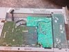
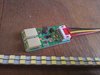
Got this working monitor from a friend free yesterday but all the ccfl bulbs seems to be dead. So i am planning to convert those ccfl to led. The pcb consists of 3 separate boards from my image img 090901. My led conversion kit requires me to look for enable on off pin and DIM pin. But on the board there is no marking of enable on off or any on the pcb silk screen.
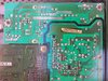
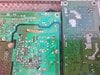
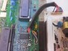
Looking at the power board and inverter board from img 091042. On power board, there is one row of 9 pins with label CN 701 and black color wire is pin 1 being nearest to the ground screw hole while grey color wire is pin 9. On inverter board, the grey color wire pin 9 is nearest to label CN807.
Next i searched for pwm chip OZ964GN datasheet from https://www.alldatasheet.com/view.js...chword=OZ964GN
Found out pin 3 is enable and pin 14 is DIM. Using an analog multimeter i trace back continuity of pin 3 of pwm to pin 1 black wire on power board. However, i was unable to find the connecting pin when i probe pin 14 to trace back to power board. There is no schematic for this monitor when i google. Can someone kind enough to help me on this?
 

Attachments

  • IMG_20201203_090901.jpg
    IMG_20201203_090901.jpg
    344.6 KB · Views: 6
  • IMG_20201203_091017.jpg
    IMG_20201203_091017.jpg
    373.3 KB · Views: 6
  • IMG_20201203_091042.jpg
    IMG_20201203_091042.jpg
    350.8 KB · Views: 6
  • IMG_20201203_091254.jpg
    IMG_20201203_091254.jpg
    275.1 KB · Views: 7

73's de Edd

Aug 21, 2015
3,622
Joined
Aug 21, 2015
Messages
3,622
Sir mikey5791 . . . . .

¿ NOW-I-ASK-YOUSE-WHASSAMATTAH-NOW-DUZENT-ENNYONES-HEARS-WANTS-TO-HEPS-YOU-OUTS-WITH-YER-SPECIFICALLY-UNIQUE-CONUNDRUM ?

(Try reading that above as effortlessly as the now all too familiar " Aoccdrnig to a rschearch at Cmabrigde Uinervtisy, it deosn't . . . .ya-da-ya-da-ya . . . . . ." Maybe I should have ALSO reversed several letters ? . . . but with the readings sole saving grace, in having been the use of dashes.)


Got your ears on ? . . . .when so . . . then try . . . .

http://bbcsfx.acropolis.org.uk/assets/07023361.wav

Since I'm probably going to POP your bubble.
Do duly note that DELL highly proclaimed of the high brigntness and SNOW WHITE display screen of that model, when being initially marketed.,
Furthermore, look at the inverter board of your now exposed unit, you see 3 lamp inverters on the board , don't you ?
Well, then look at the multiple sets of HV rated BLUE disc capacitors, carrying the AC drive to the CF tube connectors. Looks like you have 6 tubes so those are being DUAL inverters. Thats the spread out light output that one might expect on a 27 or 32 in screen.
Now your PAST experience, as being documented here, is dealing with the use of just two LED strips illuminating into TOP and BOTTOM LUCITE strips of a like 20 "ish size display.
With it incorporating VERY important optical-mechanical design aspects of initially dispersing apart initial pinpoints of LED lights illumination and THEN logarithmic dispersion of light from both TOP, downwards to vertically center mid point and BOTTOM, upwards to vertically central mid point .
That gives a uniform brightness to the white translucent plastic backdrop that then shines its UNIFORMLY ILLUMINATED white lght thru the LCD pixel matrix.
Have a design boo-boo and the backgrounds white illumination is brite at the ends and noticably dimmed at the center.
A fuller teardown of the display unit, will reveal the CFL tubes and the proper spacing apart of the six tubes. But its not as simple as with bigger screens LEDS as they also have special diffusive lens caps on them.

Your sleuthing of the DIM and ENable pins of the controller IC was being exactly correct at the controller proper, but the path back to the CN701 connector was using a higher value of interconnective resistor(s) than you might have expected. ( You have to visually trace out their connective foil paths on the board, with an ohmmeters aid.)

Your potential use of 4 or six LED strips with their LED controllers might solve the brightness ilumination situation, but then you are left to solve the / any overall uniformity of illumination disparity.
BTW on your past purchased strips, did you notice those clear special lateral dispersal lens caps being on each of them ?
upload_2020-12-9_13-50-29.png


Thaaaaaaaasssssit . . . . . .

73's de Edd . . . . . .


.

Why do they lock up those gas station bathrooms ? . . . . . are they afraid that someone is going to break into those suckers and clean them ?

.
+++++++++++++++++++++++++++++++++++++++++++++++++++++++++++++++++++++++++++++++++++++++++++++++++++++++++++++++++++
 
Last edited:

mikey5791

Jun 7, 2013
174
Joined
Jun 7, 2013
Messages
174
Sir 73's de Edd,
Appreciate your reply. It is strange that no one else respond to my post maybe because this is such a "pain in the ass" model.
Replying to your last question, the led does not seem to have any dispersing lens. They are just the square yellow type and there are 42 leds on each strip. Refer attached image of the conversion kit.
 

Attachments

  • IMG_20201210_101247.jpg
    IMG_20201210_101247.jpg
    231.7 KB · Views: 5
Top