Maker Pro
Maker Pro

Help needed to design a simple circuit

enoughwealth

Feb 4, 2010
6
Joined
Feb 4, 2010
Messages
6
Hi, I'm new here and need to some help designing a simple circuit to build a Peltier (TEC) cooler add-on for my Meade DSI Pro II CCD camera,

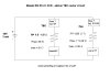
I've ordered a cheap TEC (TEC1-12709) which is rated at max 100W, 12 V (DC?) and 1.3-1.5 Ohms. The current is varied to control the amount of dT between the hot and cold sides of the TEC), with a max of approx. 8 Amps. I don't expect to run the TEC at maximum, as I don't want to cool my CCD camera below the dew point.

I've bought a heatsink/fan unit to attach to the hot side of the TEC unit, which is rated at 0.04 Amps (+/- 10%) and 12 V DC, which I figure means the R is 300 Ohm?

I'd like to run the wires from the TEC and fan into a recycled PC tower box, where I will mount an on-off switch and TEC control (rheostat?), fuses etc. onto the back of one of the HDD slot panels. Power will either be supplied from the PC power supply (V?, Current?) or I'll install a power board inside the empty PC box and use a plug pack to power the TEC/fan circuit (eg. 12V 4500mA? - I have some old plug packs sitting around eg. 12V 500 mA, 15V 1500 mA etc. I'll buy a new plug pack if needed).

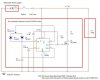
I figure I'll need to put the TEC and fan in parallel, and have a fuse for each (8A for the TEC and 0.045 A for the fan). The rheostat(? current control) I assume goes in series with the TEC so I can adjust the dT produced, but there probably needs to be some sort of 'balancing' in the circuit or else the current to the fan would go up as the TEC is turned 'down', causing the fuse to blow...

My basic circuit idea is attached, please comment and suggest what other 'bits' are needed to make this idea work...
 

Attachments

  • circuit.jpg
    circuit.jpg
    41.5 KB · Views: 3,102

(*steve*)

¡sǝpodᴉʇuɐ ǝɥʇ ɹɐǝɥd
Moderator
Jan 21, 2010
25,510
Joined
Jan 21, 2010
Messages
25,510
Is this for a telescope?

A rheostat (a term I've not heard in a while) will not do what you want.

I would guess that you want a temperature control, and that control should use pulse width modulation with a limited rate of change for the mark/space ratio as I am aware that peltier devices don't like rapid changes in current (it can cause some form of thermal shock I think)

You can fuse the entire circuit with a 15 A fuse, a separate fuse for the fan is not warranted. You always overrate the fuse because you want it to only blow if there is a serious fault.

There is no need for a resistor in series with the fan.

The battery would be called on to supply a maximum current of around 8A.

A 7Ah battery would probably last several hours, unless the peltier was running flat out all the time.

The hard part is the temperature controller for the peltier.
 

enoughwealth

Feb 4, 2010
6
Joined
Feb 4, 2010
Messages
6
Yes, its to be added to my telescope setup. The DSI is an uncooled CCD camera, which runs at about 6 degC above ambient. Every 6 degC drop in CCD temp reduces the dark noise by about 50%, so cooling the DSI's heatsink enough to drop the CCD chip temp 20 degC would reduce thermal noise by about 90%. I don't want to do a more complex internal, temp controlled hack of the DSI, so in this case the TEC is simply intended to cool the heatsink of the DSI by 20 degC or less (I don't want to chill the camera below the dew point, especially the front of the CCD chip!

As the CCD chip already has a temp sensor, the current chip temp is displayed in my imaging software. So I don't need to dynamically switch the Peltier TEC to a set temp - I just want to be able to manually turn it (and the fan) on and off, and to run the TEC at something less than max if the chip temp looks like dropping too much.

Given the TEC can be run at max 8A while the fan is only rated at 40 mA, won't using a circuit with a 15A fuse and both items in parallel risk blowing up the fan? If I just connect a 12V 'plug pack' power supply (eg. 1500 mA rated) to these items, how do I calculate the split of current that will go through each? (I think the R of the TEC varies with current provided to it?)

I've found lots of complex circuit diagrams for TEC controllers, but I'm hoping for something a lot simpler (ie, without any temp measurement and control, just manually turning the circuit off and on and control the current flowing through the Peltier (while keeping the fan clost to 12V, 0.04 A when the circuit is 'on').

ps. Do I need to run the TEC and fan from a battery? I was hoping to use it with one of the surplus 'plug pack' power transformers I have lying around, or possibly the power supply built in to an old 386 tower PC that I will gut and use to house my 'scope accessory controls.
 

(*steve*)

¡sǝpodᴉʇuɐ ǝɥʇ ɹɐǝɥd
Moderator
Jan 21, 2010
25,510
Joined
Jan 21, 2010
Messages
25,510
Heh, thought it might be for a CCD attached to a telescope :)

OK, you need to imagine electricity like water. Voltage is the pressure, current is the rate it's flowing, and resistance is, well, resistance.

Your fan and TEC are both rated to operate at the same voltage (pressure). Placing them in a circuit is fine. One requires more current (flow rate) than the other. Neither will be damaged (just as turning on one tap harder than another will not damage either).

The problem is that you need a power source (water source) capable of supplying the required current (flow rate) whilst maintaining the voltage (pressure). In your case you have a total current requirement that is 8A + 0.04A = 8.04A -- we can just call it 8A). If your battery pack can only supply 1.5A, it clearly cannot supply 8A and therefore it won't work. In fact the plugpack will probably die a horrible smoking death.

You are best off having some form of temperature control, and also preferably one which doesn't turn the power off and on slowly tot he TEC as that will cause thermal stress and eventually break it.

You need a power supply capable of supplying an 8A load (and a 7Ah sealed lead acid battery is ideal) Depending on how well the cold end of the TEC and the camera are insulated, the average current draw may well be far less than 8A.

A "cheap" solution would be to have a 555 timer with a variable duty cycle, driving a mosfet to control the average current. You could manually monitor the temperature of the camera and adjust (slowly) as required to keep it correct.

Having a large variable resistor as you initially suggested would waste a huge amount of energy, get extremely hot, and (due to the power requirement) would probably be unobtainable.

Please point me at some of these other, more complex circuits, and I may be able to suggest something simpler (It will also tell e a lot more about the drive requirements of the TEC).
 

enoughwealth

Feb 4, 2010
6
Joined
Feb 4, 2010
Messages
6
Looking around the 'net there are rheostats available that can handle 100W, but I suspect they are more like the $40-$100+ ones I've seen advertised, not the $0.40 ones from Jaycar!

So, it probably is cheaper and better to build a constant current controller circuit using electronics as you suggest. I sample diagram I've found is
http://freecircuitdiagram.com/2009/07/10/linear-tec-thermo-electric-cooler-driver/
BUT it is more complicated that I need/want as it includes temp sensor feedback to control the TEC. I'll monitor the CCD chip temp and manually 'turn down' the Peltier cooler if the chip temp starts to drop too low. So for the control circuit I only need an on-off switch, power supply for the TEC and fan (looks like I'll end up using the Tevion battery pack I have already - its rated as 3.7V 8800 mAh, but has various outputs available such as 12V 2000 mAh, 16V 4000 mAh etc. I can't understand why the mAh increases as the Voltage goes up, rather than vice versa! If it's not powerful enough, I'll buy a 12V boat battery to run all my 12V 'scope accessories)

Any advice is appreciated - I can manage to stick some components onto a bread board and wire them together, but I'll need a circuit diagram and an exact shopping list of parts to use ;)
 

(*steve*)

¡sǝpodᴉʇuɐ ǝɥʇ ɹɐǝɥd
Moderator
Jan 21, 2010
25,510
Joined
Jan 21, 2010
Messages
25,510
How about this. It's a simple PWM controller. Place your TEC where the fan is shown here.

You may need to choose an alternative mosfet with higher current rating (look for something that can handle say 15 amps or more continuously, and has a low Rdson.

http://www.dprg.org/tutorials/2005-11a/index.html
 
Last edited:

(*steve*)

¡sǝpodᴉʇuɐ ǝɥʇ ɹɐǝɥd
Moderator
Jan 21, 2010
25,510
Joined
Jan 21, 2010
Messages
25,510
There should have been :eek:
 

Resqueline

Jul 31, 2009
2,848
Joined
Jul 31, 2009
Messages
2,848
Running on batteries you certainly want a switch-mode (PWM) regulator, but it should have a filtered output as TEC's have a lowered efficiency when running on "raw" PWM.
Also look around for adjustable output switch-mode plug packs. I know they exist, the question is how low they'll go and exactly how powerful they are.
 

enoughwealth

Feb 4, 2010
6
Joined
Feb 4, 2010
Messages
6
Thanks for the advice Steve, the circuit looks easy enough to assemble. I guess the +3-15V for the 555 is connected in parallel with the TEC +ve ('motor' in the ciruit diagram) and all the earth symbols in the diagram are connected to the -ve of the battery pack?

I'm not too fussed about loss of TEC efficiency at this stage, as I don't expect to run it at maximum or it may cool the CCD below dew point and cause condensation problems (I'm trying to avoid having to drill holes in the CCD camera case and install a dry air flush at this stage). What do I need to do to filter the PWM anyhow?

Rather than using a battery, would it be possible to use the power supply in the old PC tower case I'm going to use to house the circuits for my various auxilliary 'scope electronics and control switches and knobs...
 

Attachments

  • circuit v2.jpg
    circuit v2.jpg
    55.1 KB · Views: 1,569
Last edited:

(*steve*)

¡sǝpodᴉʇuɐ ǝɥʇ ɹɐǝɥd
Moderator
Jan 21, 2010
25,510
Joined
Jan 21, 2010
Messages
25,510
Just make sure that the 12V rail from the PC power supply is rated at 8A. The 5V rail is probably rated at 20 to 30 A, but the 12V rail is usually much less. It is quite probably that it will be more than you require, but make sure.

Most PC power supplies tend to "act up" if there is no load on the 5V rail. Some require this load (say 500 mA) to even start up. The same is true of the 12V rail, but generally to a lesser extent.

The main issues are whether the PSU will start up, and what the regulation is like. The worst case scenario is that the 12V rail goes high under no-load conditions and fries the 555.
 

enoughwealth

Feb 4, 2010
6
Joined
Feb 4, 2010
Messages
6
Plan B?

I bought some of the parts for the circuit from a local electronics hobbyist store (Jaycar), but they didn't have the MOSFET (1RFZ46N) or diodes (1N5818) so I'm a bit stuck (knowing how to substitute components is 'black magic' to me).

I thought I may just buy a suitable 12V controller kit such as this 5A 12V Speed Controller/Lamp Dimmer (~$12 + $6P+P !):

http://www.siliconchip.com.au/cms/A_111001/article.html
for sale here
http://shop.voltelectronics.com.au/new-12v-motor-speed-light-dimmer-controller-kit.html

or this 10A 12VDC Motor Speed Controller Kit (~$24)

http://www.jaycar.com.au/productView.asp?ID=KC5225

I almost bought the Jaycar 10A 12VDC motor speed controller kit today, but it was out of stock.

Any advice before I go ahead and mail order the 5A 12V Speed Controller/Lamp Dimmer kit?
 
Top