Maker Pro
Maker Pro

help getting started with new design

rgd80

Feb 25, 2013
1
Joined
Feb 25, 2013
Messages
1
Hi all,

Where do I start:confused:?

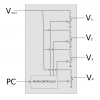
I have attached an image of a electronics module I want to make.

Basically it takes a voltage input and outputs four voltages for which each can be anywhere between 0%(or ground) and 100% of the input voltage.

I want each voltage output to be computer controlled and my very basic understanding is that I can do this with a microcontroller. Again, forgive my limited knowledge, I think I can do this by using a voltage divider on each output and have the microcontroller control a digital potentiometer inside each divider.

I have been thinking along these lines but I have not found a digipot that can work at voltages >15V. My input voltage will be typically 20V DC but may go as high as 200V DC.

Also the outputs will drive static loads (i.e. just electrodes - I am forming an electrostatic field with the four voltages inside a vacuum chamber).

Thanks in advance.
 

Attachments

  • breakout.png
    breakout.png
    20.6 KB · Views: 180

pwdixon

Oct 14, 2012
52
Joined
Oct 14, 2012
Messages
52
You could use something like a port per voltage and use high voltage mosfets to switch a number of resistors to ground if you can tolerate a digitised output voltage. You might be able to use a R/2R ladder network to save using precision resistors but I haven't thought that through yet.

Alternatively, as I doubt you will be able to find a high voltage digital pot, I guess you could drive motors linked to pots but that would be quite excessive a solution as you would also need to control each motor setting by monitoring the output voltages and using a control loop. You could of course use stepper motors but then you would still end up digitising the position and you might as well use my original method which at least is all electronic and not mechanical.
 

CocaCola

Apr 7, 2012
3,635
Joined
Apr 7, 2012
Messages
3,635
I have been thinking along these lines but I have not found a digipot that can work at voltages >15V. My input voltage will be typically 20V DC but may go as high as 200V DC.

So you use the appropriate voltage dividers and adjust down to safe levels...
 

Electrobrains

Jan 2, 2012
259
Joined
Jan 2, 2012
Messages
259
Very interesting application!

I think pwdixon's idea with basically a high voltage D/A converter could work well. But I suspect that it would need a lot of components and a bigger uC with many I/Os to be able to reach some accuracy for 4 channels.

My idea is a low-cost, compact circuit with "adaptive voltage regulators".
As I understand, the application neither demands fast reaction, nor high output power.

The circuit shown below is based on a low-cost uC. It has rather slow, routine constructed PWM or PDM (Pulse Density Modulated) output pulses that are Low-Pass filtered to give a smooth control voltage to a MOSFET transistor. The MOSFET acts as a Voltage/Resistance converter and will control T2, that acts as a linear series regulator.

The output voltages of the channels are brought to A/D converters that will give the measured data for the control loops of each channel (the programmer needs to have some understanding of Control Theory). The dynamic response of the regulators is much influenced by the RC product, that needs to be quite high to be able to filter the PWM signal.

The circuit could work in this way as a programmable 4-channel High Voltage Regulator.

To be able to get the Voltage Splitting function (% of supply voltage), the Supply Voltage is also brought to the uC as a Supply Reference Signal. The uC can then calculate the real Reference Signal for the control loop when the ratio (%) is given from somewhere.

I think this circuit could work well in some applications. It will have a few weaknesses though: The line and load regulations will not be very good because of the slow uC system response. To directly regulate 50/60 or 100/120Hz ripple, for sure you would need a much stronger uC with several built-in PWM modules running at high frequency. In this case, I have assumed that the high voltage power rail does not change voltage very rapidly.

Another concern with this circuit is the rather sharp VgsON knee of the MOSFET (made for switching rather than V/R conversion), that wouldn't allow for much dynamic of the PWM signal. There might be "softer" MOSFETs available, or some further dc adaption could be made to better fit the linear area of the MOSFET.
But maybe the laggardness of the RC filter would be enough to set the operating point in a good way.

4_ch_HV_Splitter-Regulator.JPG
 
Top