Robert Hill
- Mar 5, 2015
- 112
- Joined
- Mar 5, 2015
- Messages
- 112
Hi all, I'm being driven mad by a cricuit i'm trying to build which just isn't working!
Here's the schematics for what i'm building.
This is the first part, the idea is that by turning the trimmer POT (VR1) you can set the desired level of DC at the DC+ and DC-

The problem I'm having is that the maximum voltage I can get at the DC points is 0.87 volts and no matter how much I turn the POT the minimum I can get is about 0.74 volts (TR1 gets mega hot at this point as well!). As far as I can tell the resistance of the POT is changing when I turn the screw.
Anyone got any suggestions as to what might cause this issue? This part of the circuit appeared to work properly at one point but no longer does.
The second part of the circuit joins on to the right of the schematic above, it is:
This is an astable multivibrator whos peak to peak is supposed to be the same at the DC level set previously.
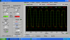
However, the AC+ and AC- points never give the desired square wave. Is there a way to test this circuit to find out what has gone wrong? Anywhere obvious to start looking?
Any help much appreciated as it is pretty disheartening given how much time i've put in that I just can't get it to work properly!
Thanks,
Here's the schematics for what i'm building.
This is the first part, the idea is that by turning the trimmer POT (VR1) you can set the desired level of DC at the DC+ and DC-
The problem I'm having is that the maximum voltage I can get at the DC points is 0.87 volts and no matter how much I turn the POT the minimum I can get is about 0.74 volts (TR1 gets mega hot at this point as well!). As far as I can tell the resistance of the POT is changing when I turn the screw.
Anyone got any suggestions as to what might cause this issue? This part of the circuit appeared to work properly at one point but no longer does.
The second part of the circuit joins on to the right of the schematic above, it is:
This is an astable multivibrator whos peak to peak is supposed to be the same at the DC level set previously.
However, the AC+ and AC- points never give the desired square wave. Is there a way to test this circuit to find out what has gone wrong? Anywhere obvious to start looking?
Any help much appreciated as it is pretty disheartening given how much time i've put in that I just can't get it to work properly!
Thanks,