I am trying to build a clock based on (an outdated MSP430 version of) this: http://www.sharebrained.com/chronulator/
The meters required are either 50uA or 100uA. I have a couple of sets of meters that I would like to use, but they seem to be of the wrong rating - i.e. I can't achieve full scale deflection
Well, that's not exactly true. By eliminating (quite by accident originally) a resistor, the meters do go full scale and approximate the correct time, but they appear to move more on the lower end than they do on the higher end. What I mean by that is if the scale is divided into 12 equal parts, with 12 on one end, six in the middle and 12 on the other end (I have no idea why 12 is on both ends) each "increment" should increase the needle by one division. Instead, on the left side of six, each "increment" actually moves the needle a little more than one division, so that six "increments" is pretty much on the seventh division. On the right hand side, each "increment" moves slight less than one division, so that on the twelfth "increment" the needle does in fact point to 12.
My first question is would a VU meter, specifically designed for that purpose, exist this non-linearity on it's own, or should it work like any other 50-100uA meter movement?
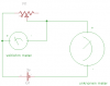
My second question is a little embarrassing. I've been doing electronic service for twenty years, but I have never had need to do this. To determine the current needed for full scale deflection on the meter, I hooked up the circuit in the attached image. I advanced the potentiometer until I had full scale deflection on the meter and measured the voltage drop across the potentiometer. Then I removed the potentiometer and measured it's resistance. Using Ohm's Law I=E/R where E=2.53v and R=7.82k I calculated the current at 0.000323529 or 325uA give or take.
So that's right, right? Is there any way to use that meter in a 50 or 100uA circuit? I thought that maybe a shunt resistor would work, but before I tried figuring that out, I wanted to make sure I was figuring the meter correctly...
Any help would be great. Thanks...
Oh... and by the way...does anybody know how to get a meter symbol in Eagle CAD?
The meters required are either 50uA or 100uA. I have a couple of sets of meters that I would like to use, but they seem to be of the wrong rating - i.e. I can't achieve full scale deflection
Well, that's not exactly true. By eliminating (quite by accident originally) a resistor, the meters do go full scale and approximate the correct time, but they appear to move more on the lower end than they do on the higher end. What I mean by that is if the scale is divided into 12 equal parts, with 12 on one end, six in the middle and 12 on the other end (I have no idea why 12 is on both ends) each "increment" should increase the needle by one division. Instead, on the left side of six, each "increment" actually moves the needle a little more than one division, so that six "increments" is pretty much on the seventh division. On the right hand side, each "increment" moves slight less than one division, so that on the twelfth "increment" the needle does in fact point to 12.
My first question is would a VU meter, specifically designed for that purpose, exist this non-linearity on it's own, or should it work like any other 50-100uA meter movement?
My second question is a little embarrassing. I've been doing electronic service for twenty years, but I have never had need to do this. To determine the current needed for full scale deflection on the meter, I hooked up the circuit in the attached image. I advanced the potentiometer until I had full scale deflection on the meter and measured the voltage drop across the potentiometer. Then I removed the potentiometer and measured it's resistance. Using Ohm's Law I=E/R where E=2.53v and R=7.82k I calculated the current at 0.000323529 or 325uA give or take.
So that's right, right? Is there any way to use that meter in a 50 or 100uA circuit? I thought that maybe a shunt resistor would work, but before I tried figuring that out, I wanted to make sure I was figuring the meter correctly...
Any help would be great. Thanks...
Oh... and by the way...does anybody know how to get a meter symbol in Eagle CAD?