Maker Pro
Maker Pro

Hello, can somebody help wich transistor is like bfg520

Audioguru

Sep 24, 2016
3,656
Joined
Sep 24, 2016
Messages
3,656
I remove lpf , so now tuning to transistor q2 is from 88 to 108Mhz, is okej now to build, normal when i change the value of varicap i get those result
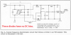
The frequency range is wrong. In a superheterodyne FM radio that has a 10.7MHz IF the local oscillator must tune from 77.3MHz to 97.3MHz or tune from 98.7MHz to 118.7MHz except a little lower in Japan where I think FM station frequencies go down to 76MHz.
 

(*steve*)

¡sǝpodᴉʇuɐ ǝɥʇ ɹɐǝɥd
Moderator
Jan 21, 2010
25,510
Joined
Jan 21, 2010
Messages
25,510
I thought the FM band was 88 to 108 MHz?
 

michael1978

Mar 17, 2012
388
Joined
Mar 17, 2012
Messages
388
Tuning range seems OK. My simulation work with the BB515.
Have you built a physical circuit?
May i ask you something else, how can i couple mutuli nductance, can you help me please, you know good this simulator,
 

WHONOES

May 20, 2017
1,217
Joined
May 20, 2017
Messages
1,217
May i ask you something else, how can i couple mutuli nductance, can you help me please, you know good this simulator,
Hi, I'm back after a few days in the lake district.
Why do you want to connect multiple inductances?
Thanks. Yes the Simetrix simulator is very good, been using it for years.
 

michael1978

Mar 17, 2012
388
Joined
Mar 17, 2012
Messages
388
Hi, I'm back after a few days in the lake district.
Why do you want to connect multiple inductances?
Thanks. Yes the Simetrix simulator is very good, been using it for years.
Sorry for late, i was no in internet, what is dat multiple inductance? wha they do,

I will like to ask you do you know something radio to design, i make rf amplifier, local oscillator, if amplifier, only i dont know so much how to demulate
 

WHONOES

May 20, 2017
1,217
Joined
May 20, 2017
Messages
1,217

michael1978

Mar 17, 2012
388
Joined
Mar 17, 2012
Messages
388
It was you who asked about multiple inductances in post #124.

Try the link below for an introduction to FM receivers.
http://www.arrl.org/files/file/Technology/tis/info/pdf/8506025.pdf
THANKS MAN, yes that was true for mutual inductance coupling but i solved, thank you,
but i dont know how to make transformer COUPLING, can you please (when you have time) to make it, i making one but is not working, i have trouble to make transformer i send you the schematicrf amp and detector.png
can you please help with transformer from that file,
 
Last edited:

Audioguru

Sep 24, 2016
3,656
Joined
Sep 24, 2016
Messages
3,656
It looks like you copied the Foster Seeley discriminator wrong:
 

Attachments

  • foster seeley discriminator.png
    foster seeley discriminator.png
    36.8 KB · Views: 13

michael1978

Mar 17, 2012
388
Joined
Mar 17, 2012
Messages
388

Attachments

  • rename detecor in asc.txt
    2.7 KB · Views: 8

WHONOES

May 20, 2017
1,217
Joined
May 20, 2017
Messages
1,217
I don't know enough about IF amplifiers to comment which is why I directed you to that web site. I am sure there are others if only you take the trouble to search for them.
 

michael1978

Mar 17, 2012
388
Joined
Mar 17, 2012
Messages
388
I don't know enough about IF amplifiers to comment which is why I directed you to that web site. I am sure there are others if only you take the trouble to search for them.
no no i am loking to build one receiver just that, nothing else and i am almost finish
 

michael1978

Mar 17, 2012
388
Joined
Mar 17, 2012
Messages
388
no no i am loking to build one receiver just that, nothing else and i am almost finish
Hi sir, do you know this circuit with Jfet, do you know, wich form tuned circuits inductor and capacitor, do you see the circuit is inductor with 470p tuned of wich capacitor ??:(
 

Audioguru

Sep 24, 2016
3,656
Joined
Sep 24, 2016
Messages
3,656
Michael, it looks like you are trying to simulate a circuit, not build the circuit.

You make many errors when you copy a schematic. Here are my attachments:
1) This discriminator from the book has no strong DC bias on the diodes like your circuit has.
2) Your ratio detector is completely different than the book and has a crazy RC at its output.
3) Your inductors do not have tuning capacitors.
 

Attachments

  • discriminator DC bias.png
    discriminator DC bias.png
    164.5 KB · Views: 8
  • ratio detector.png
    ratio detector.png
    96.3 KB · Views: 8
  • discriminator tuned inductors.png
    discriminator tuned inductors.png
    73.1 KB · Views: 8

michael1978

Mar 17, 2012
388
Joined
Mar 17, 2012
Messages
388
Michael, it looks like you are trying to simulate a circuit, not build the circuit.

You make many errors when you copy a schematic. Here are my attachments:
1) This discriminator from the book has no strong DC bias on the diodes like your circuit has.
2) Your ratio detector is completely different than the book and has a crazy RC at its output.
3) Your inductors do not have tuning capacitors.
But you say i miss the capacitor to be tuned perfect(i will solve), now i know, but can you tell me, wich capacitor and inductore create 5.1Mhz, can you tell me please so i can change the resonance please thanks
 

michael1978

Mar 17, 2012
388
Joined
Mar 17, 2012
Messages
388
But you say i miss the capacitor to be tuned perfect(i will solve), now i know, but can you tell me, wich capacitor and inductore create 5.1Mhz, can you tell me please so i can change the resonance to 10.7Mhz, like you said, is tuned to 5.1Mhz please thanks
DISCRIMINATOR circuit,
and why they can pass audio signal what wrong with ratiod detector
 

Audioguru

Sep 24, 2016
3,656
Joined
Sep 24, 2016
Messages
3,656
can you tell me, wich capacitor and inductore create 5.1Mhz, can you tell me please so i can change the resonance please thanks
The IF for an FM radio is 10.7MHz but your simulation has a generator frequency of 5.1MHz. It is easy to calculate the inductance and capacitance for an LC to resonate at a selected frequency.

DISCRIMINATOR circuit, and why they can pass audio signal what wrong with ratiod detector
The discriminator circuit you posted has a low power Jfet with a fairly high output impedance trying to drive an 8 ohm speaker through a 2.2uF capacitor that has a value much too low for audio into an 8 ohm speaker. The Jfet and 2.2uF capacitor will be able to feed audio into the input of an audio power amplifier that can drive the speaker.

The ratio detector you posted has a 0.1pF capacitor which is an extremely low value feeding an 8 ohm speaker which is impossible. The 0.1pF capacitor can be calculated as 0.1μF (100nF) to feed wideband audio into the input of an audio power amplifier that has a 100k input resistance. The amplifier can drive the speaker.
 

michael1978

Mar 17, 2012
388
Joined
Mar 17, 2012
Messages
388
The IF for an FM radio is 10.7MHz but your simulation has a generator frequency of 5.1MHz. It is easy to calculate the inductance and capacitance for an LC to resonate at a selected frequency.


The discriminator circuit you posted has a low power Jfet with a fairly high output impedance trying to drive an 8 ohm speaker through a 2.2uF capacitor that has a value much too low for audio into an 8 ohm speaker. The Jfet and 2.2uF capacitor will be able to feed audio into the input of an audio power amplifier that can drive the speaker.

The ratio detector you posted has a 0.1pF capacitor which is an extremely low value feeding an 8 ohm speaker which is impossible. The 0.1pF capacitor can be calculated as 0.1μF (100nF) to feed wideband audio into the input of an audio power amplifier that has a 100k input resistance. The amplifier can drive the speaker.
No Audioguru like example I make 0.1P(it was 0.1 AND resistor OF 500K)(i change to self experiments i did it,)

Yes is easy i know, but wich are the capacitor(i dont know wich capacitor, tell me please wich capacitor and i gonna change self, wich inductor with capacitor and gonna make 10.7? i am trying to calculate is 470p of in parallel 2 capactor from 470p i make experment but i cant find the solution (and also i make experiment i put the 8OHM resistor it was 27K with capacitor) so i remove is working transformer, just stay to change to make 10.7MHZ this how to do it?, thanks man
 
Top