Braeden Hamson
- Feb 18, 2016
- 240
- Joined
- Feb 18, 2016
- Messages
- 240
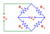
I dug a little isometric joystick or "pointing stick" out of an old Lenovo. If you're still confused its a pressure sensitive controller. I think its four strain gauges wired up in a wheatstone bridge. As shown in this patent
http://patentimages.storage.googleapis.com/US6509890B1/US06509890-20030121-D00002.png
and full patent
https://www.google.com/patents/US6509890
I can't quite make sense of what they're talking about. I probed mine a little, there are 4 wires, the resistance between two of them was 2.550 k Ω. When i put pressure on the stick it changed to 2.600k Ω. That change seems a little small. That makes me think there has to be some extra trickery to get this thing to work.
So if you guys have any ideas, let me know. In the patent they're using voltage comparators any clue why?