Maker Pro
Maker Pro

Generating a 5V Clock Signal

JHarmon

Jun 30, 2012
20
Joined
Jun 30, 2012
Messages
20
(Please excuse any stupid questions, I'm new to this)

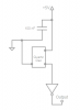
I'm trying to generate a 5V clock signal to be used with this 74LS00 series binary counter:
http://www.futurlec.com/74LS/74LS161.shtml

I need a 4 MHz signal, but I'm really struggling to get any clock designs to work. What kind of circuit will be the easiest way to accomplish this?
 

JHarmon

Jun 30, 2012
20
Joined
Jun 30, 2012
Messages
20
Embarrassingly enough, I have a crystal oscillator like that that I've been working with...

But for some reason, the circuit I have it in won't produce a frequency that will trigger the counter. I have the output buffed through a 74LS00 NAND gate (to get it to a 0V to 5V square signal), then connected to the clock pin on my counter.

I know my counter circuit is working. I tried pulsing it at 1 MHz with a 555 timer, and they worked fine (but I can't get a 555 timer to 4 MHz).

Have I wired the oscillator incorrectly? I have no connection to pin #1, +5V to pin #14, and pin #7 is grounded.

Or will this require a more complicated circuit?
 

hexreader

Apr 21, 2011
135
Joined
Apr 21, 2011
Messages
135
I have no connection to pin #1, +5V to pin #14, and pin #7 is grounded.
Sounds good to me. You make no mention of pin 8 output to your circuit, but I am assuming that is connected.

I reckon that should be all you need.

All I can think of to try further might be:

Put a 0.1uF decoupling capacitor across 5v supply as close as possible to the oscillator. I trust you have a decoupling capacitor close to each chip in your circuit.

Try connecting one end of a 1K resistor to pin 1, then the other end to +5V
Try connecting one end of a 1K resistor to pin 1, then the other end to 0V
(pin 1 is output enable on some oscillators and I guess they will default to enable with no connection, but I am not certain)

Check the 5V supply line with a voltmeter, in case the oscillator is drawing more current than the power supply can give.

All of these are clutching at straws - I can't think why it does not just work

EDIT: ....... oh... and welcome to the forum :) I am fairly new here too
 
Last edited:

JHarmon

Jun 30, 2012
20
Joined
Jun 30, 2012
Messages
20
I'll play with my filters and see what I can do... I'll reduce as much noise as possible and see if I can fix it.

Thanks for your help, and thanks for the warm welcome haha
 

davenn

Moderator
Sep 5, 2009
14,260
Joined
Sep 5, 2009
Messages
14,260
I'll play with my filters and see what I can do... I'll reduce as much noise as possible and see if I can fix it.

Thanks for your help, and thanks for the warm welcome haha

Also a welcome from me to Electronics Point :)

what filters ?

sections of a HEX inverter are more commonly used for buffering Here's one I use with several sections to boost the output ( my one is operating at 10MHz) .....

attachment.php


those osc modules "just work" apply power and get an output :)
ensure you have identified the pins correctly .... pin 1 is by the square cut corner

there is the possibility that the sensitivity of your freq counter isnt good enough to measure the output from the oscillator

Dave
 

Attachments

  • buffer.GIF
    buffer.GIF
    4.5 KB · Views: 545

(*steve*)

¡sǝpodᴉʇuɐ ǝɥʇ ɹɐǝɥd
Moderator
Jan 21, 2010
25,510
Joined
Jan 21, 2010
Messages
25,510
The easiest way to generate a clock signal like this is to use a device designed to do it.

Sure, it's not as much fun as doing it yourself, and probably more expensive, but you can be pretty sure it will work.

Look here.

edit: a re-read suggests you may be using one of these (or similar) perhaps you can give us the part number or a link to the datasheet so we can check how it's used.
 
Last edited:

davenn

Moderator
Sep 5, 2009
14,260
Joined
Sep 5, 2009
Messages
14,260
The easiest way to generate a clock signal like this is to use a device designed to do it.

Sure, it's not as much fun as doing it yourself, and probably more expensive, but you can be pretty sure it will work.

Look here.

edit: a re-read suggests you may be using one of these (or similar) perhaps you can give us the part number or a link to the datasheet so we can check how it's used.

yes thats what HEXreader linked to above same type of item, different site

we are just trying to make sure the OP has wired his one up correctly :)

Dave

haha I was typing as you edited ;)
 

JHarmon

Jun 30, 2012
20
Joined
Jun 30, 2012
Messages
20
Anybody see a mistake in this? (Not very good with this diagramming program...)

Edit: Square corner is top-left (pin #1)
 

Attachments

  • Capture.PNG
    Capture.PNG
    5.8 KB · Views: 178

hexreader

Apr 21, 2011
135
Joined
Apr 21, 2011
Messages
135
Looks good to me!

I would say that the inverter is unnecessary, as the oscillator probably has high drive capability.

... but leave the inverter in if it makes you happy, as it does no harm other than to waste a chip.
 

gorgon

Jun 6, 2011
603
Joined
Jun 6, 2011
Messages
603
Anybody see a mistake in this? (Not very good with this diagramming program...)

Edit: Square corner is top-left (pin #1)

Not if you see the oscillator from the top.
The question is, does it work? If not, have you connected it different before?
Have you shorted the output to 5V or 0V?

How do you know it doesn't work?

I know it's of little help but I've used a number of canned oscillators in the past, and never experienced any problems with them.
Are they brand new? From a decent distributor?

TOK ;)
 

JHarmon

Jun 30, 2012
20
Joined
Jun 30, 2012
Messages
20
New oscillator, never been used, It is wired to the binary counters (Which I tested at 1 MHz and they work fine), but still nothing... The counters' datasheet says I should be able to use a signal up to 25 MHz.

I'm really confused... Seems so simple, right?
 

(*steve*)

¡sǝpodᴉʇuɐ ǝɥʇ ɹɐǝɥd
Moderator
Jan 21, 2010
25,510
Joined
Jan 21, 2010
Messages
25,510
Can we have the *exact* part number of the device you're using?

Can you measure the current it draws when powered up?

Some of these devices use the 4th pin to enable the oscillator.
 

MrEE

Apr 13, 2012
84
Joined
Apr 13, 2012
Messages
84
Do you have a scope to check the oscillator is working? another way to check oscillation is to measure the DC voltage of the output pin. You should read 1/2 the Vcc value or about 2.5V in this case.
Typically (on most oscillators) the output is enabled when the enable input is left open or tied high. Always check the datasheet for the component you are working with or plan to use. At 4MHz the output should be pretty nice and square so I'd remove the inverter altogether, but you say you use a NAND gate. How did you connect the two inputs? One of the input should be tied high and the other one goes to the osc. output.
there isn't much else I can think of. You should be able to get that baby oscillating unless of course it's damaged (for some reason, say it got dropped).
 

JHarmon

Jun 30, 2012
20
Joined
Jun 30, 2012
Messages
20
Fixed it... Thanks for everyone's help!!!!

(Happened to noticed an unplugged wire while measuring voltages and such to answer (*steve*) and MrEE... *facepalm*)
 
Top