You shouldn't switch neutral.
Whether or not this switch is suitable for switching the maid to your devices depends on its voltage and current ratings and those of the device being switched.
If the foot switch is suitably rated, then use it as intended. If not, a relay may be an option, but you need to provide low voltage to switch the relay and more mains wiring and an enclosure.
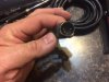
I'm sorry, but on my phone the images are not particularly clear. Maybe someone else can verify the information from them.
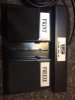
Looks like 15amp , 125-250VAC...
That said... I'm unsure how it's actually constructed internally, and what the pinout of that connector would be.
I see 6 pins, and two pedals.
As mentioned previously, you do not wan't to switch neutral. You always switch the hot side.
That being said... without knowing the pinout, if you connect the Hot wire to the wrong pin, you could potentially make the foot pedal assembly live.
I would not use that enclosure, nor would I recommend it, unless you can determine with certainty what the pinout is, and that there is at *least* a contact for Neutral in addition to ground. Would be much better if there was also a ground contact...