Maker Pro
Maker Pro

Flurescent Lamp possible ballast issues

boinc21

May 19, 2019
3
Joined
May 19, 2019
Messages
3
Hi all,

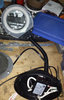
I’m a beginner with electronics, we have this lamp and we changed the bulb and it didn’t turn on, I had the bulb replaced in case it was defective same thing. I tried different wallplugs in case. I have contacted the company about getting a new ballast but they do not provide any.

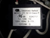
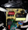
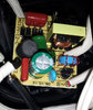
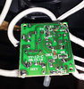
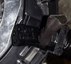
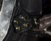
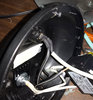
There is a Electronic Ballast Model : YY-12-D Class P. I tried to look for this online. I took it apart, and I have attached some pictures. I couldn’t see anything really wrong, maybe F1 I think it’s a fuse? But the capacitors and resistors look okay, as well as the circuit traces, if I am not mistaken. Again I’m beginner to this, so I don’t know most of the components. I do have access to a voltmeter, and a soldering iron. I am not sure what to test if anyone can help out please.

Thanks
boinc21
 

Attachments

  • 1.jpg
    1.jpg
    42.9 KB · Views: 14
  • 2.jpg
    2.jpg
    53.7 KB · Views: 13
  • 3.jpg
    3.jpg
    150.2 KB · Views: 15
  • 4.jpg
    4.jpg
    188.2 KB · Views: 14
  • 5.jpg
    5.jpg
    181.8 KB · Views: 13

FuZZ1L0G1C

Mar 25, 2014
366
Joined
Mar 25, 2014
Messages
366
First check if your lamp-holder contacts are making proper connection.
They may be stretched open from wear or oxidized.
If your 'voltmeter' is a multi-meter, meaning it can measure ohms, volts, amps (at least), and hopefully has a diode test function and capacitance range as well, you can start with the cord, fuse F1, move to transformer continuity, rectifier diodes, capacitors.
MAINS POWER OFF AND UNPLUGGED
  1. Check continuity from cord's plug to supply wires in lamp base. See '2' below for how.Check across fuse terminals on ohms or continuity buzzer. 0 or very low reading (or beep) = fuse good. Otherwise renew fuse.
  2. On ohms scale (pref auto range) check transformer primary and secondary winding. OL = open, i.e. faulty.
  3. With meter on Ω (ohms), continuity, or diode test, measure each diode one-by one, incl. reversing test leads.
  4. On diode test you should read (about) 500-800 mV (0.5-0.8 V) forward voltage drop.
  5. The caps don't look blown (top safety hat bulging), but not always an indication.
  6. You would probably have to unsolder the caps to test off board, as other components may affect reading.
  7. If you have C range, check that C reading closely matches value on cap body.
  8. Otherwise check ohms in one direction, ++ and -- then on DC volts reverse the leads.
  9. If good, a larger cap should show discharge, whereas the small values will discharge very quickly.
  10. On resistance Ω, a cap will show ohms increasing in value.
  11. A ballast (aka choke) is an auto-transformer coil, used to step up mains voltage to a lethal level.
Some non wire-contacting tricks to check the ballast:​
  • With power on, tube in, feel temp on casing of ballast. Should be warm, not cold or cooking.
  • If tar is leaking out, or very hot, then ballast may have a short. Cold probably open circuit. Buy another.
  • Got an AM radio? A working ballast should have enough EM radiation to cause a mains buzz (hum) close to AM radio.
Remember the circuit generates high voltage when on.
 
Last edited:

boinc21

May 19, 2019
3
Joined
May 19, 2019
Messages
3
Thank you very much FuZZ1L0G1C, that is a lot of information I will be looking into and trying out! I do have access to a multimeter, sorry I always mix up the terms. Good to know that the caps have to be unsoldered to try out. I am just curious for testing the ohms in one direction for the caps, that means that like both probes on the each seperate bottom pin? The AM radio tip is neat. Yes with it on it can be very dangerous. Thank you very much again!
 

Harald Kapp

Moderator
Moderator
Nov 17, 2011
13,719
Joined
Nov 17, 2011
Messages
13,719
I am just curious for testing the ohms in one direction for the caps,
You don't measure resistance ("ohms") for capacitors. Unless the capacitor is defect, the resistance is very high (infinite for an ideal capacitor).
If your multimeter has an option to measure capacitance, use that. Otherwise it is not easy to measure capacitance without proper equipment.

that means that like both probes on the each seperate bottom pin?
Right, this is valid for any 2-pin component. One probe per pin. You may have to observe polarity (+,-) with polarized components like electrolytic capacitors, diodes etc.
Not with non polarized componnets like e.g. resistors, transformers etc.

There is a fuse F1 on the pcb (image 3, top left). Check that first for continuity (0 Ω).
 

Bluejets

Oct 5, 2014
6,920
Joined
Oct 5, 2014
Messages
6,920
I'd be looking for the obvious i.e. where the lamp plugs in to the 4 pin socket. They are round pins and notorious for burning out from the heat of the lamp.
Perhaps trace down to the ballast ( electronic..no tar in these fellas.) and check for the 2 heaters from there .
 

boinc21

May 19, 2019
3
Joined
May 19, 2019
Messages
3
Thank you Harald Kapp, and Bluejets. I did some testing in ohms, on a fix setting as there is no auto option, the fuse is okay, and a couple of other components, I don't have a cadence meter, that is really good to know. I also checked the 4 pin socket, and even used a pick to check for corrosion, it seemed good. I took a panel off to have a close look, and it looks like they put a capacitor just before it.

I would have to research more on testing the plug.

The ballast does get warm when the lamp is plugged in.
Could a switch go bad? I would have to take it apart, but it looks really fixed, as the way its wired. I was looking for a way, if it unplugs easy to jump the wires, but I didn't find anything yet.

Thank you
 

Attachments

  • 6.jpg
    6.jpg
    51 KB · Views: 4
  • 7.jpg
    7.jpg
    44 KB · Views: 3
  • 8.jpg
    8.jpg
    53.2 KB · Views: 4

Bluejets

Oct 5, 2014
6,920
Joined
Oct 5, 2014
Messages
6,920
Could a switch go bad? I would have to take it apart, but it looks really fixed, as the way its wired.

If the switch is not working any components would hardly get "warm".

Not an ideal way of testing really especially given the mains voltage component.

Did you test continuity of the wiring from the tube socket pins down to the electronic ballast..?

Did you check for heater circuits on the tube..? ( there are 2 at low ohms ....maybe 4 ohm)

Did you test the incoming mains lead for continuity...? Give each end a good wriggle in case there is an intermittent break.

All the above continuity tests should be possible as each end of the wire would be accessible in each case.
 

FuZZ1L0G1C

Mar 25, 2014
366
Joined
Mar 25, 2014
Messages
366
The 'caps on ohms scale' test is not intended to measure resistance directly.
On a meter (preferably analogue), the series voltage of the resistance test supplies a small charge to the cap.
You could also charge it with a battery less than WVDC rating of cap. ++&-- for polarized caps.
Testing the DC voltage should show needle drop lower as it discharges.
The resistance, usually set on a few MΩ will rise as the plates charge.
More visible on bigger capacitance values.
 
Top