Maker Pro
Maker Pro

Fishing trolley faulty....again

scooby

Oct 16, 2017
20
Joined
Oct 16, 2017
Messages
20
Hi everyone, loaded up the trolley the other day, got halfway across the car park and it ground to a halt.I got this trolley several years ago second hand and as far as i know it's the original battery. On the trolley handle are three lights, green, amber and red. In use, unless on flat tarmac the amber light is invariably lit and any sort of slope caused the red light to appear. I always put this down to the battery capacity diminishing, so bought a new battery. No change! Thinking that maybe the brushes are worn i connected the battery directly to the motor and it turns just fine. The only thing it will do now is maybe turn the wheels slowly if i raise them from the ground. Once again, any help would be greatly appreciated.
 

Bluejets

Oct 5, 2014
6,927
Joined
Oct 5, 2014
Messages
6,927
Sounds like a bad connection somewhere but without any further photos or details , not much we can do.

You have to remember, we have no idea as to what you have in front of you and, being holidays I forgot to charge the crystal ball batteries. :):)

Look for corrosion anywhere or burnt cable or a hot spot on a joint when the load is on.
 

scooby

Oct 16, 2017
20
Joined
Oct 16, 2017
Messages
20
Thanks bluejets, i've tried uploading pics but haven't been able to, hoping one of the kids will pop in and show me how, i managed it last time somehow. When i try it says an error occured, will keep trying.
 

73's de Edd

Aug 21, 2015
3,622
Joined
Aug 21, 2015
Messages
3,622
Sir scooby . . . . . (doo ? )

That might be a tougher one, this time around , with your professed and limited apprehension of electronics circuitry.

On the units controller board I only see 3 discrete surface mount micro transistors and a 3 terminal regulator IC.
(And those 3 transistors just might be associated with their being used as LED drivers for your 3 states of indicator lights.)
Sooooooo the system just might be making a glorified power control with the 3 term regulator component and the main two POWER
semiconductors being heat sinked at the end of the board.
Please submit their part numbers for our consideration.
They presently must not be totally " crunched " or the units motor would be running full speed with no control . . . as before..

Its not being relevant to your present situation of not running but . . . .
? . . . . . the 2 power units show to be dry of any silicone grease for max thermal conduction to their heat sink, and are mica insulators used ?

EARLIER INFO PHOTOS . . . . .
https://www.electronicspoint.com/forums/threads/fishing-trolley-will-not-stop.285950/


73's de Edd . . . . .

You know what I did before I married?
Anything I wanted to.
 

scooby

Oct 16, 2017
20
Joined
Oct 16, 2017
Messages
20
Thanks edd, the semi-conductor nos are irf3205 p618p 52ln (the one i replaced before) and mbr 20100ct aka318. what i think is the regulator component has L7805cv G410k Vb CHN 414 written on it.There is a strip of material between the power units and the heatsink, but you are right, nothing on one side! I should add that the circuit board appears unchanged from before.
 

davenn

Moderator
Sep 5, 2009
14,262
Joined
Sep 5, 2009
Messages
14,262
i've tried uploading pics but haven't been able to, hoping one of the kids will pop in and show me how,

make sure the images are .jpg and are resized to no bigger than 1024x768 (preferably a bit smaller 800x600) and compressed so they are 100kb or less

otherwise you will get error msgs

Dave
 

scooby

Oct 16, 2017
20
Joined
Oct 16, 2017
Messages
20
Thanks Davenn, hopefully this works.


IMG_0697 - Edited.jpg IMG_0699 - Edited.jpg IMG_0695 - Edited.jpg

IMG_0699 - Edited.jpg


IMG_0695 - Edited.jpg


[mod note... put images inline]
 
Last edited by a moderator:

Bluejets

Oct 5, 2014
6,927
Joined
Oct 5, 2014
Messages
6,927
I can see two fairly hefty leads in the background with spade terminals which appear to be ok.( red and black)

What about motor connections, battery connections any overload unit, any isolator connections etc. etc.

Boards are pretty pictures but unless something you can see obviously blown/corroded/unusual then neither do we.
 

scooby

Oct 16, 2017
20
Joined
Oct 16, 2017
Messages
20
Thanks bluejets, i have checked them already and they are fine.In the absence of anything obvious it makes me suspect the mosfet i installed. My question is, can a failing fet produce the symptons i've described?
 

Bluejets

Oct 5, 2014
6,927
Joined
Oct 5, 2014
Messages
6,927
It is a common error for newbies to start to blame failed electronic components.
Mostly, the components are long lasting and faults occur in more common "mechanical" devices such as switches and connectors.
It is possible you never really corrected the fault from your first attempt.
That was why I asked you to check other things as above.
 

73's de Edd

Aug 21, 2015
3,622
Joined
Aug 21, 2015
Messages
3,622
Sir scooby . . . . .

Your first encounter was a cake walk, compared to your evolved situation this time.
You had a shorted Drain to Source on the power FET and that effectively had the unit running full speed, just as soon as the unit was turned on.
So you replaced the shorted POWER FET and solved the problem the first time , and the unit worked properly up until now, where you have the power FET not now being able to power the drive motor in an incremental manner.

How about the battery type used on this unit voltage ??? and current capacity ??? wise . . .would you conside it being a no maintenance gell cell type of battery with 2 push on connectors, or is this on up into the small motorcycle lead acid category of battery ?

Is the " new" battery verified as being good and "hot" enough to have the equivalent " overspeed " condition that you experienced before when the motor was effectively operating on full battery voltage ?

Now in respect as to how this unit is designed for its operation, I can see the IC2 3 term 7805 regulator being used as a variable constant current source type of control and the POWER FET then handling the BRUTE POWER motor speed aspect.
BUT . . . the 20K speed pot value would not correlate into that designed. circuitry.
Then there is the capability of having the IC2 7805 regulator being able to give a varying drive to the POWER FET, if its center ground terminal is lifted, and fed a varying voltage reference. Then the varying drive to the POWER FET acomplishes your power control of the motor.

OR the IC2 7805 regulator is actually being used for providing a STABLE 5VDC supply for a remoted microprocessor that receives and feeds back into the 8 pin connector to the end of the shown PC board. ( maybe located within the section with the display LED lights )

Take a DVM or analog voltage metering and place in DC mode and use the battery negative terminal as ground meter probe referencing. Then power up the unit and see if the full battery voltage is on the left IC2 terminal and what voltage output is being on the far right IC2 terminal. If the output is 5VDC , we are not having the IC used in the manner mentioned above . BUT . . .if you find other than 5VDC at the far right terminal and is being variable as you adjust the speed control pot, that is how they are using the IC2 for control.

INFO . . .
On your pot, it should stop between 270 degree rotational limits . . .not spin freely thru 360 degrees . . . it must have a metal tab stop on the pot rotor that is /has bent / misaligned. Since that stop tab is intended to limit its extremes rotary travel as it meets two separate indentations in the metal control cover at the 270 degree rotary displacements .
Check it o o o o o u u u u u t t t t !

Your new photo . . .3rd down . . . has revealed a new component not being visible before .
A 6 pin mini chip at the right side of the large black elecrolytic condenser.
Pass back any numbering upon it, or to its side pcb ( like IC2 was assigned to its component ).
Typically, I usually see these as being dual med pwr fets in one case or being an optical isolator.

Your motor could be a commutated rotor with 2-4 internal permanant magnets as the field portion .
Or it coulfd be using a commutated rotor with wire wound field electromagnetic coils . Since your
unit is using that TO-220 cased diode akin to the FETS, we can see this as being a series witred arrangement
DC motor as described in the second condition.
The power diode then supresses back EMF as the commutator brushes intermittently break contacts .

Fill us in on the 6 pin unit ID and the IC 2 7805 output voltages .


73's de Edd . . . . .

Doctors say I have multiple personalities . . . . .but WE don't agree with them.

. . .
 

Harald Kapp

Moderator
Moderator
Nov 17, 2011
13,727
Joined
Nov 17, 2011
Messages
13,727
As the unit is a few years old, a "good" suspect is the big electrolytic capacitor. If it has lost a noticeable part of its capacitance, the supply voltage to the control circuit may not be stable enough to allow correct operation. This can easily be checked by connecting a new capacitor (same capacitance and voltage) in parallel to the existing one.
While you're at it it will not hurt to replace the smaller electrolytic capacitors, too.
 

scooby

Oct 16, 2017
20
Joined
Oct 16, 2017
Messages
20
The unit next to the capacitor has 8 pins (not visible) and the microprocessor is tucked under the large capacitor. The pics are better than my eyesight so i'll upload them as not all the lettering is clear. Will check the other bits tomorrow and report, thank's everyone.8 pin.JPG microprocessor.JPG
 

scooby

Oct 16, 2017
20
Joined
Oct 16, 2017
Messages
20
Hi Edd, the voltage on the left leg is 12v and the right leg is 5v. Nothing changes as i rotate the speed control. Another potential problem has come to light. I was inspecting my soldering efforts on the fet i replaced and noticed it is different from the existing one! I've lifted it from the board and will get the correct one :rolleyes:. Another couple of pics are inbound!
 
Last edited:

73's de Edd

Aug 21, 2015
3,622
Joined
Aug 21, 2015
Messages
3,622
Sir scooby . . . . .


Where you g o o o o o o o ?

Indeed . . . in using the first photo, it does reveal the in and out electrolytic decoupling filters and the center tab goes to that ground plane and one portion of the the regulator output goes to the end BROWN wire of the end connector.

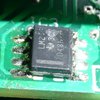
The newest photos reveal what seems to be a ST Electronics 990xx series Brushed DC motor driver and what once appeared to be a 6 pin IC, is now a 8 pin unit and a commercial temp rated LM258/358 dual op amp.The E cap was hiding the full case profile .

I take it that the final photo is of the original IRF3205. Which is just their standard version and having laser etched markings.
BUT . . . the photo of the replacement, is letting me see but just the slightest trace of white in its center marking . . . therefore . . . it looks almost like it has been running hotter 'n hell.
How do / did the case appearances seem to you, at install time versus the present time condition ?
I see that original unit as bing a standard IRF3205 150 watt / 98amp unit.
Its also available as a Z version with a 170 watt / 110 amp unit.
If you step up to a IRF3305 its being a 330 watt / 140 amp unit.

TECH SPEC REFERENCING . . . .
https://alltransistors.com/mosfet/c...50&uds=55&id=98&qg=146&rds=0.008&caps=TO220AB


If this unit still has all parts installed and can run with wheels floating, why not do some metering at the power FET gate.
Have meter BLACK lead to battery ground and use the RED meter lead to the gate and test in DC voltage mode to see if there is any voltage change as the power is flipped on and the speed control is run thru its limits.
Then switch metering to AC voltage mode and do the same tests.
Pass on the observed voltage changes.
If nothing definitive . . . . . move back to the LM 258 and try the identical testing on its pins 1 and 7.

If you are lucky enought to have found a varying change on the FET GATE, you just might need a FET change out due to the present one having a blown GATE.

CASE REFERENCING . . . .
upload_2019-4-25_5-20-19.png

By your description, the POWER FET seems to have used a silicone membrane insulator pad between it and the heat sink, and they are usually pink, grey, red or white. But . . . . I additionally use a film of silicone grease on both sides.
With time and heat and compression, but no silicone grease, the transistor will stick to the membrane and usually tear if an attempt to remove the transistor is made.

https://www.digikey.ca/en/product-h...41-commercial-grade-electrical-insulator-pads

Thaaaaaaaaassssssit . . .

73's de Edd . . . . .


Show me a man with both feet firmly on the ground, and I’ll show you a man who can’t get his pants off.
 
Top