Maker Pro
Maker Pro

Farberware Food Processor FP3000FBS

Chas

Oct 26, 2017
50
Joined
Oct 26, 2017
Messages
50
Hello all, my first posting so be gentle!

I am very much at the amateur end of the electronics spectrum. My dabblings have mainly been in passive guitar electrics, classic cars (pre 1985, before ECU's took over) and simple electronic repairs i.e. re-soldering failed joints in old audio amps etc.

Anyhow, this is what I am currently working on:

Farberware FP3000FBS food processor.
Approximately 1 year old (out of warranty).
It was working fine, then one day my other half went to use it and it was completely dead.
No lights come on, no noises, no burning smells, no smoke, just totally dead and unresponsive.
It should operate by pushing one of the four front panel buttons to select speed/ mixture function. These now do nothing.
I've taken it apart, nothing looks amiss and none of the components show signs of overheating or failing.
There's a main circuit board/ controller, and a satellite board with four micro-switches on it to operate the 4 functions.
There's a soldered fuse on the circuit board that is intact (it shows continuity when I put my multimeter across the pins).
The motor works fine when power (125v) is applied to it.
The safety pin switch is functioning as it should (only allows the processor to work when the bowls are latched into place).

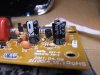
Pictures below of the circuit boards.

Here's the main controller board (front and back):

IMG_20171025_212536.jpg

IMG_20171025_212556.jpg

And here's the satellite front panel switch board (front and back):

IMG_20171025_212629.jpg IMG_20171025_212652_1.jpg


I've done some rudimentary testing using my multimeter.

With power applied, and the "negative" terminal of the multimeter attached to the neutral wire of the AC input, I am getting readings of 125v where the black wire is connected to the circuit board, and also where the brown wire is connected. The black wire on the circuit board appears to be the main power for the board, and the brown wire is the power for the motor. The brown wire is connected to one pin of the black relay, and it appears that the relay should activate to allow the circuit to complete to the white wire on the board (see the heavy silver tracks on the underside of the main board. This white wire goes to the safety switch (which is working correctly) and then to the neutral power cord wire. If I jump the brown wire directly to the neutral wire, the motor operates. Therefore, what I can deduce so far is that the relay is not switching, or whatever part of the circuit is controlling the relay is not doing its job.

I've also tested voltages around the board, and they vary from 125v to 60v near to the main black wire input, then seem to be around 0.4v around the main IC and the rest of the circuit board.

I've also tested the satellite switch board, and when the correct pin on the IC is monitored for a switch press, the voltage increases from 0.4 to 0.5v (all four switches are operational).

This is as far as my abilities can take me. With my basic understanding of circuits, I suspect one or more components is/ are not allowing the circuit to be completed, hence the unit appearing to be dead. But which component is it likely to be?

I am wondering if either the main IC has failed, or one of the capacitors, or a diode/ transistor.

These are the big items on the board that look to have the most affect:

IMG_20171025_005420.jpg IMG_20171025_212755.jpg IMG_20171025_212824.jpg IMG_20171025_005454.jpg

I think I have covered most of the basics and supplied as much information as I muster! If I have missed anything, or further information is needed, please ask and I'll do my best to supply it.

Can anyone help guide me as to the next steps I should take? Any more diagnostics I should be carrying out to identify the likely culprit? Most of the components appear to be available new, so if I can narrow it down to the most likely failed components I can start replacing them and hopefully get this food processor working again.

Many thanks in advance for any help and/ or guidance!
 

kellys_eye

Jun 25, 2010
6,514
Joined
Jun 25, 2010
Messages
6,514
Approximately 1 year old (out of warranty)
Not aware of the US-based warranty system but here in the UK a 12 month warranty refusla would be laughed out of court as the ruling says (not in actual words) that the item 'must be fit for purpose' and 12 months lifespan clearly doesn't represent any such thing so perhaps approaching the manufacturers with a polite inquiry may get it fixed???

If not then the board is fitted with a capacitive-dropper circuit to get the low DC required to power the board (probably 12V as this is needed for the relay). The 12V is also applied to a regulator (the device on the black heatsink) to get the 5V required for the PIC controller chip. Check for 12V and 5V on the regulator pins (careful not to short circuit them).

The relay is driven by the small transistor beside it with the diode wored across the coil for back emf protection.

Check the the positive end of the diode (with the black band) is around 12V DC and the negative end switches from 12V to around 1V when the relay should operate. If it doesn't do so then check for the controlling signal at the base of the transistor (one end of R18).

If that signal is present then Q3 could be dud.

We can also trace further 'back' but, for now, see where the above gets you.
 

dorke

Jun 20, 2015
2,342
Joined
Jun 20, 2015
Messages
2,342
"I've also tested voltages around the board, and they vary from 125v to 60v near to the main black wire input, then seem to be around 0.4v around the main IC and the rest of the circuit board.

I've also tested the satellite switch board, and when the correct pin on the IC is monitored for a switch press, the voltage increases from 0.4 to 0.5v (all four switches are operational)."

The above suggest a problem with the low voltage DC on the board.
The μC chip should have DVC of 2.2-5.5V on the pins shown below,
please check it with your meter on DCV,carefully don't short out!
What do you get?
Check the voltages(DCV) on the 3 caps marked -blue,and 2 diodes marked -green.
what do you get?

IMG_20171025_212536.jpg
 

Chas

Oct 26, 2017
50
Joined
Oct 26, 2017
Messages
50
Kellys_eye and Dorke, thank you so much for your responses. I appreciate both you helping me very much.

Kellys_eye, I am actually from the UK and only recently emigrated to the USA, and from what I gather warranties are kind of similar here to the UK in terms of an item being fit for purpose. I should elaborate more on the warranty aspect with regards to this food processor as because it failed, the company sent a replacement. Unfortunately, they no longer have the same model nor a similar replacement with the same capacity. The replacement they sent is a 10 cup, whereas the unit that failed is a 12 cup. Furthermore, the replacement lacks some of the features (specific blades, dough hook) that the Farberware had. I know nothing about baking, but according to my other half this makes a difference to dishes that they make. Though the 10 cup mostly suffices, there are times when the capacity is insufficient and they need the attachments that it doesn't have, hence trying to get this 12 cup Farberware working again.

I've tested the unit to get results from the specified areas requested by you both. Other that where the AC connects to the board and near to the large resistors where readings of 60 - 125 VAC could be obtained, the rest of the board seems to have very low voltage. I could only get readings by setting my multi-meter's range to 2 VDC. Anything higher barely registered. Also, in my post above I think I was misreading the Multi-meter when I was recording voltages of 0.4 and 0.5. I believe I should have been reading them as 0.004 and 0.005.

Here are the readings I obtained with the MM set to 2 VDC:

TR1 Regulator: No readings from any of the pins
D7 Diode: +'ve end = 0.003, -'ve end = seems to cycle between 0.002 - 0.004
R18 Resistor: Brown end = 0.007, Gold end = 0.002
U Chip: Black arrow pin in pic = 0.007, Red arrow pin = cycles between 0.002 - 0.004

3 Caps marked in blue:
CE3 = 0.006/7 (both pins)
CE2 = 0.006/7 (both pins)
CE1 = 0.006/9 one pin, the other pin = 0.003/4

Diodes marked in green:
D21: one pin = 0.04, other pin = 0.06
D6: both pins = 0.05

From what I seem to be understanding, the voltage for the circuit is too low for it to function? If this is the case, does this narrow down the component(s) that could be the culprit? Or are there any more tests I need to carry out before replacing components?

Looking forward to further guidance, and thanks again for your help.
 
Last edited:

Chas

Oct 26, 2017
50
Joined
Oct 26, 2017
Messages
50
I can't seem to edit my post above, so I will make the corrections here:

Diodes marked in green:
D21: one pin = 0.004, other pin = 0.006
D6: both pins = 0.005
 

dorke

Jun 20, 2015
2,342
Joined
Jun 20, 2015
Messages
2,342
Please check the following pairs of color(both probes on each point of color) in ACV(200),
careful, 125VAC expected(blender connected to mains)!

In this order: Blue ,yellow,red.
What do you get?

IMG_20171025_212556.jpg
 

Chas

Oct 26, 2017
50
Joined
Oct 26, 2017
Messages
50
Dorke, thanks again for responding and helping.

I checked the voltages at the points you specified above with the food processor connected to 125v mains. Multimeter set to 200 VAC, then pins connected to each pair of colours. Here are the results:

Blue = 123v
Yellow = 123v
Red = 1.3v

I assume you are checking to see if the voltages are being dropped down correctly? Or are present on the various circuits on the board?

Hopefully these voltage readings may help shed some light into what is (or isn't) going on with this circuit.

Looking forward to your further response.
 

dorke

Jun 20, 2015
2,342
Joined
Jun 20, 2015
Messages
2,342
Yes,
Checking for correct drooping of ACV.

The Red reading is too low.
That makes the biggest brownish capacitor a suspect(next to the yellow cubed one).
But there can be other issues.

Please recheck the Red voltage (ACV),
and add the pink(ACV) ,

Please make these DCV measurments:
1. Light-blue (DCV).
2. Voltage on DZ1(DCV) : "+" on the "black line mark"(cathode), "-" on the other(anode).

Disconnect from power and measure in ohm-diode mode test DZ1 in both directions.

Can you also take a good closeup photo of the CE1,it's top looks a bit bulged.

What is written on U1and Q1?

IMG_20171025_212556-2.jpg
 

Chas

Oct 26, 2017
50
Joined
Oct 26, 2017
Messages
50
Thanks again Dorke. I've tested the board again and measured the following (my responses in red):

Please recheck the Red voltage (ACV),
and add the pink(ACV)


MM set to 200 VAC:
Red = 1.3
Pink = 55


Please make these DCV measurments:
1. Light-blue (DCV).
2. Voltage on DZ1(DCV) : "+" on the "black line mark"(cathode), "-" on the other(anode).


MM set to 2 VDC:

Light Blue = 0.36
DZ1 = 0.01
DZ1 with MM set to 200m = 9.9


Disconnect from power and measure in ohm-diode mode test DZ1 in both directions.


I assume that ohm-diode mode test is the following setting?

DSCF7867.JPG


With the MM on that setting, this is what it is reading on DZ-1:

With Red Probe on black (+'ve) line = 001
With black probe on black (+'ve) line = 001


Can you also take a good closeup photo of the CE1,it's top looks a bit bulged.

Pics of CE1:

DSCF7866.JPG
DSCF7864.JPG
DSCF7862.JPG
DSCF7860.JPG

What is written on U1and Q1?

From what I could read:

U1 = L78L05 A GE520 (and with "e3" in a circle)

Q1 = BR 9014 Cp29f

Picture showing U1 and Q1 below:

DSCF7865.JPG

Any other information or readings you need, please ask away. Also, I am curious to learn this process of fault finding, so if it's not too much trouble to ask, please do explain what should be happening on the board and what some of these findings/ readings are showing. I would love to learn more!


View attachment 37088[/QUOTE]
 

Attachments

  • DSCF7866.JPG
    DSCF7866.JPG
    196.5 KB · Views: 84

dorke

Jun 20, 2015
2,342
Joined
Jun 20, 2015
Messages
2,342
"this is what it is reading on DZ-1:

With Red Probe on black (+'ve) line = 001
With black probe on black (+'ve) line = 001 "

This looks like a short on DZ1.(can be the Zener,or other parts which are paralleled to it)
What is written on DZ1?

How are your soldering skills?
De-solder and Lift one leg of DZ1 and check the diode alone (like you did before).
What do you get?

Repeat the test on the pads of DZ1(with the diode leg lifted).
What do you get?
 
Last edited:

Chas

Oct 26, 2017
50
Joined
Oct 26, 2017
Messages
50
This looks like a short on DZ1.(can be the Zener,or other parts which are paralleled to it)
What is written on DZ1?

Very hard to read as the writing is minuscule and wraps around under the component. In the end I un-soldered DZ-1 from the board and used my camera to zoom in and read the letters and numbers. I think this is what is written on DZ-1:

IN4742A
5T (or might be ST)

Pic below was taken on maximum zoom:


IMG_20171028_231632[1].jpg
How are your soldering skills?

Rudimentary, though good enough to un-solder and re-solder most of the component types on this circuit board. I may struggle with the main IC chip, more from nerves and inexperience I should add, so hopefully I won't have to un-solder it. I have a basic soldering station with variable temp control that seems up to the job for most small tasks I've done with it, plus a spring action solder sucker.

De-solder and Lift one leg of DZ1 and check the diode alone (like you did before).
What do you get?


Using the diode test mode on my MM, initially the reading seemed to scramble higher numbers for a split second, then falls to 001, holds on 001 for a second or so, then drops to zero. It did this for both polarities using the MM probes.

N.B. After the above test I re-soldered DZ1 back onto the board and re-tested. This time it gave a steady reading of 001 (both polarities) as it did previously.


Repeat the test on the pads of DZ1(with the diode leg lifted).
What do you get?[/QUOTE]


First reading = 1276
Reversing the probes = 471

Is this shedding more light on what might be the fault? Thank you again for helping :)
 

dorke

Jun 20, 2015
2,342
Joined
Jun 20, 2015
Messages
2,342
Since DZ1 shows 001 on both directions outside of the board we have found the problem,
a shorted zener diode.
Get a new one, ohm it before you solder it in.

Please check diodes D1-D4 the same way( in circuit)
 

Chas

Oct 26, 2017
50
Joined
Oct 26, 2017
Messages
50
Since DZ1 shows 001 on both directions outside of the board we have found the problem,
a shorted zener diode.
Get a new one, ohm it before you solder it in.

Please check diodes D1-D4 the same way( in circuit)

Excellent detective work Dorke! Many thanks!

I will order some new diodes. Cheapest I found came in a pack of ten. Are these suitable?

https://www.ebay.com/itm/10x-10pcs-...535023&hash=item3af47ef7fe:g:GxUAAOSw2TdZ4632

I will also check the D1 - D4 diodes and report back.

Thank you again!
 

Chas

Oct 26, 2017
50
Joined
Oct 26, 2017
Messages
50
Diodes ordered!

I thought I might have been jumping the gun when I re-soldered DZ1 back onto the board last night... Doh! I de-soldered and lifted one leg, then carried out the Diode mode test on diodes D1 - D5. I added D5 because, well, might as well do them all!

Thus with one leg lifted on DZ1, no power to the board, MM set to Diode Mode Test:

D1 (red probe to grey stripe end) = 1, Probes reversed = 439

D2 (red probe to grey stripe end) =1, Probes reversed = 436

D3 (red probe to grey stripe end) = 1, Probes reversed = 440

D4 (red probe to grey stripe end) = 1, Probes reversed = 440

D5 (red probe to grey stripe end) = 1, Probes reversed = 428

Also note that when tested with the red probe to the grey stripe end, the MM displays a high number then goes straight to "1".

Also a quick question on solder temp. My soldering iron is variable between 220 and 450 degrees centigrade (how accurate it is, is another matter). Anything less than 300 and the solder doesn't melt on the tip. I was just a little concerned when I read somewhere in the specs for the IN4742A something about "solder point" being 220 degrees. I'm assuming that as per many electrical components, too high a soldering iron temp can damage the component being soldered or un-soldered. As such, can you recommend what temp I should set my iron at to be able to solder/ un-solder these components and not damage them?

Many thanks again for your help.
 

dorke

Jun 20, 2015
2,342
Joined
Jun 20, 2015
Messages
2,342
The diodes look o.K.

The DMM showing "I"(i for infinity,actually "1") means it is in the O.L.(over load) state,
it is expected in the case you described for the diodes.

This doesn't have to be infinity, so those meters which display O.L. are more "accurate" in that sense.
Here is an example a 1k ohm resistor measured in the 200 ohm range showing "I".
It is obviously in O.L. condition not infinity...
the reason "1" is used is simply because it is a numerical value ,i.e. no need to add alphabetic value to the LCD.

DMM-OL.jpg
 

dorke

Jun 20, 2015
2,342
Joined
Jun 20, 2015
Messages
2,342
About soldering,
You are correct,a too high temperature for a too long time may damage parts.

The temperature to be used is dependent of many factors including:

1.Soldered device limits and heat profile.
2.Type of heat source.
3.Type of the solder itself.
4.Type of soldering tip.
5.Type and size of the soldering place/surface.
etc.

Soldering is something most beginners/hobbyist take too lightly,while it is actually a craft that needs to be learned well and thoroughly.
This is why we have a practical soldering guide resource here at EP.
Study it it well,it will leverage your soldering knowledge and skills tremendously!
 

Chas

Oct 26, 2017
50
Joined
Oct 26, 2017
Messages
50
Thank you again for all your help and explanations Dorke, it is very much appreciated.

I will certainly check over those soldering guides and videos. I've been able to solder well enough to get by, though always felt that my skills could be a lot better. I've never got those really smooth shiny joints, mine looked more like grey pigeon poop. Saying that, I had an ancient soldering iron inherited from my father, no idea if it was any good or not. The iron I have now was bought recently, and though it's far from a top level iron, it was one of the better products reviewed during my search. When I re-soldered DZ1 back onto the board (prematurely), I surprised myself with how much better the soldering was than my efforts back in the UK. Maybe I am getting better, though I will certainly study those guides.

As soon as the diodes I ordered arrive I will solder one in place of the old DZ1. I will report back as to what happens when I try the food processor after that. Fingers crossed.
 

Chas

Oct 26, 2017
50
Joined
Oct 26, 2017
Messages
50
Update:

Faulty DZ1 diode replaced tonight (the pack of ten arrived yesterday). And...


...it's working again!

Well, not all functions appear to be working, but the food processor itself is alive and can be activated from the panel buttons. All panel four buttons activate the motor, and their corresponding diodes light for each button that is pressed. The only thing that doesn't seem to be quite right is that there should be 3 selectable speeds, plus 1 manual operation (Pulse) button. However, the motor only seems to run at one speed, whichever button is pressed. I tried measuring the voltage to the motor when each button is pressed, but I am not sure I am measuring it right. I assumed the motor would be using AC, but using the 200AC setting on my multimeter gave odd readings such as 5v. I switched it to 200VDC, and this time it gave readings of 55 VDC each time the motor was run, regardless of speed button pressed.

Regardless, it's good news that the food processor is up and running again, though quite why the speed selection has no effect I have no idea. I will ask my other half how essential those other speeds are tomorrow. Maybe it's another component that needs replacing? Any pointers to which it might be?

Also a massive thank you to Dorke for helping me to get this far. Awesome diagnostic work sir! I really appreciate your help and guidance.
 

dorke

Jun 20, 2015
2,342
Joined
Jun 20, 2015
Messages
2,342
Your are welcome,
This is what we do here, help;)

We can go on finding the fault.

First thing is to check the DC voltage on DZ1,
12VDC expected,it should be present both in the ON an OFF states.
What do you get?

Then check the DC voltage on DZ7,
12VDC expected in ON state,0V in off state.
What do you get?

Then check the DC and AC voltage on R24,
12V to 0V is expected in all states and speeds.
What do you get?
a total of 10 measurements: 5 for DC,5 for AC( in 3 speeds+pulse+off).

The indications on the photo are for the -/+ leads of the DMM's probes for each measurement,
put them on a device at the same time.
Please don't short or let the probes slip.
And be careful of the right end line voltage area!

IMG_20171025_212536-b.jpg
 
Last edited:
Top