Maker Pro
Maker Pro

Dyson DC24 Brush Roller DC Motor PCB

***Ed***

Aug 27, 2014
11
Joined
Aug 27, 2014
Messages
11
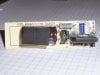
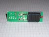
Hi, my 10 year old Dyson DC24 vacuum cleaner's brush roller stopped working during use. No burning or noises were reported. Upon inspection I found nothing visibly untoward. However there is no power output to the DC motor from the PCB which takes in 240 VAC and outputs DC of unknown voltage (a newer model has a 300 VDC motor). The PCB appears to have an open circuit 1 ohm resistor (R1 on the images, R4 on the diagram) which I think is a problem, hopefully the problem. There are no visible signs of damage. Note there is a safety switch activated by over loading the motor (I think) which I've not included in the circuit diagram for simplicity of drawing, it seems to be working OK.

I have a few questions about this circuit design:

1. What is the point of the 1 ohm resistor?
2. Why are there 3 equal value resistors in series?
3. What does the capacitor do?
4. What is the likely cause of this resistor being open circuit?

Thank you.
 

Attachments

  • Dyson DC24.jpg
    Dyson DC24.jpg
    59.5 KB · Views: 88
  • Image00002.jpg
    Image00002.jpg
    108.9 KB · Views: 82
  • Image00001.jpg
    Image00001.jpg
    104.1 KB · Views: 79
Last edited:

debe

Oct 15, 2011
278
Joined
Oct 15, 2011
Messages
278
The 1 ohm resistor is being used as a fuse &it has obviously burnt out. The other resistors & capacitor are interference supressors.
 

(*steve*)

¡sǝpodᴉʇuɐ ǝɥʇ ɹɐǝɥd
Moderator
Jan 21, 2010
25,510
Joined
Jan 21, 2010
Messages
25,510
1. What is the point of the 1 ohm resistor?

It will act as a fuse

2. Why are there 3 equal value resistors in series?

To provide sufficient voltage or power rating. In some circuits it can also be used to reduce parasitic capacitance, but that would not be the case here.

3. What does the capacitor do?

It almost certainly has a role in reducing the electrical noise generated by the motor. However it's main purpose is most likely as a filter capacitor to smooth the DC to the motor.

4. What is the likely cause of this resistor being open circuit?

Motor or capacitor shorted.
 

***Ed***

Aug 27, 2014
11
Joined
Aug 27, 2014
Messages
11

(*steve*)

¡sǝpodᴉʇuɐ ǝɥʇ ɹɐǝɥd
Moderator
Jan 21, 2010
25,510
Joined
Jan 21, 2010
Messages
25,510
Why not just use a fuse?

Because a resistor is cheaper.

Why use three resistors in series rather than one?

To provide sufficient voltage or power rating. In some circuits it can also be used to reduce parasitic capacitance, but that would not be the case here.

How should I test the motor and capacitor?

Use your multimeter on the resistance range and measure their resistance.

Tell us what they read. It may also be useful to rotate the motor a bit and read the resistance again.
 

***Ed***

Aug 27, 2014
11
Joined
Aug 27, 2014
Messages
11
Use your multimeter on the resistance range and measure their resistance.

Tell us what they read. It may also be useful to rotate the motor a bit and read the resistance again.

The capacitor resistance increases from zero and keeps increasing steadily. I stopped at around 200 Ω.

When I turn the motor I can feel it 'clicks' into position. Each position gives the following resistance:
438k
0.390k
0.092k
0.071k
0.208k
0.161k
0.258k
5.1M
open circuit
12M
4.2M
4.1M
0.44M
0.399k
0.105k
0.122k
0.204k
open circuit
0.3k
5.5M
open circuit
12M
4.15M
4.1M
then back to top
 
Last edited:

duke37

Jan 9, 2011
5,364
Joined
Jan 9, 2011
Messages
5,364
If the motor has carbon brushes, the likelyhood is that they are worn out.
If the brushes are good, then the armature is dead and a new motor is needed.

Does the motor click or is it just cogging due to the location on the pole pieces?

Edit
If an armature coil is open circuit, then the commutator often shows evidence of sparking between the segments. A 12V battery charger in series with a bulb gives a simple way of measuring the continuity of coils. There is a voltage drop between brush and segment which gives false readings on a weak meter.
 
Last edited:

***Ed***

Aug 27, 2014
11
Joined
Aug 27, 2014
Messages
11
Does the motor click or is it just cogging due to the location on the pole pieces?

A 12V battery charger in series with a bulb gives a simple way of measuring the continuity of coils.

It is not clicking, it just feels like I thought spinning the motor would feel ie not smooth but discrete like moving a magnet past another magnet.

I have a 12V battery charger. What kind of bulb should I use and what results am I looking for?
 

duke37

Jan 9, 2011
5,364
Joined
Jan 9, 2011
Messages
5,364
Cogging is due to a magnet passing a pole piece as you say. This means that there is a certain voltage necessary to get over the hump so there is a minimum speed which cannot be run below. Posh motors have the armature windings wound on a helix to average this torque out.

A sidelight bulb would do to give an indication of current. There should be current at all rotational positions. Check that the brushes are not worn out and they are free to move in their holders.

What does the commutator look like? It should be uniformly chocolate brown with no signs of arcing between segments.
 

***Ed***

Aug 27, 2014
11
Joined
Aug 27, 2014
Messages
11
What does the commutator look like? It should be uniformly chocolate brown with no signs of arcing between segments.

I read up on DC motors and can see why it is probably broken given the resistace readings - I think I should have seen low resistance on all measurements.

So I replaced the resistor and the motor and everything is fine.

Thanks for all the help. If I get a moment I'll take the old motor apart for a look after putting it in circuit with a lamp for another check. It doesn't look like one that is meant to be taken apart so this is a one way task.
 

Minder

Apr 24, 2015
3,478
Joined
Apr 24, 2015
Messages
3,478
Generally it is not recommended to simply use a resistance meter for armature resistance due to unstable readings at such a low current.
The recommended way is to lock the rotor and set up a small DC supply at a known voltage and measure current at different point around the com.
The lowest reading is taken as the armature resistance.
M.
 

Flamin Mho

Aug 7, 2020
1
Joined
Aug 7, 2020
Messages
1
Very late I know (but my DC24 just packed in so I'm on the hunt).
The large cap is to smooth the full-wave rectified mains in to something approaching DC (not for interference supression).
The 1R res is to limit inrush current to the cap when first turned on.
The 3 100k resistors in series are to discharge the cap when power is removed (for safety).
 
Top