Maker Pro
Maker Pro

Dual Speed Control Circuit

mortier

Oct 9, 2017
4
Joined
Oct 9, 2017
Messages
4
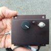
I'm hoping to reproduce a speed control circuit. It powers a 110v AC universal vacuum cleaner motor which is installed in an old-time payer piano. The electric suction motor overcomes leaks in the old foot-pump player piano. It's designed to provide two, pre-set motor speeds; a high-speed for playing, and a low speed for rewinding the piano roll (when less suction is needed). The switch-over is controlled by a micro switch attached to the piano's rewind control. The circuit has 2 potentiometers ("play" and "rewind"). Not being an electronics tech, could anyone help me?

Here's what I can read on the components:

3-Prong connector (between the 2 potentiometers): BTA12 800BW, GK2AC VU, CHN 549

Toggle Switch: 8A 125V AC

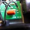
Red capacotots (?): DME-F250V, CO-104K

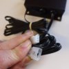
The 3 wires on the right side are labeled "NC" "NO" "C" (Normally Closed, Normally Open, Common?)

Many Thanks!

PhilP1020133.JPG P1020134.JPG P1020109.JPG P1020106.JPG P1020133.JPG P1020134.JPG P1020109.JPG P1020106.JPG P1020133.JPG P1020134.JPG P1020109.JPG P1020106.JPG
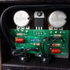
P1020133.JPG
 

Tha fios agaibh

Aug 11, 2014
2,252
Joined
Aug 11, 2014
Messages
2,252
What do you mean by reproduce? It works fine and you want to copy it?
If you are trying to restore unknown connections, I can't say for certain how it works without seeing entire circuit, but it looks like jack with two wires connects to power source in series with the load.

The three wires from No, Nc, and C go to their designed switch terminals that toggles the speed (on the roll?) fast and slow.

If you can't find more info on this board, I would disassemble it to see what's on the other side of the board.
 

Minder

Apr 24, 2015
3,478
Joined
Apr 24, 2015
Messages
3,478
If wishing to reproduce it, it seems to be a very easy circuit to reverse engineer?
M.
 

73's de Edd

Aug 21, 2015
3,622
Joined
Aug 21, 2015
Messages
3,622
SIr mortier . . . .

YES . . . . . do you want to make another like unit, or is this one being inoperative ?

If an inoperative unit and considering the pull of that motor and no hidden fuses blown, the most likely part to fail is the BTA12 triac.
If replicating the unit, I see all parts being available but having to make a micro variance in using 150K linear pots instead of those 160K units shown.
Also, all of the numbering from the centrally located BLUE diode is being needed.

73's de Edd
 

mortier

Oct 9, 2017
4
Joined
Oct 9, 2017
Messages
4
This circuit works, but it is no longer being manufactured, so I would like to make another. I will try to read the blue diode.

Phil
 

mortier

Oct 9, 2017
4
Joined
Oct 9, 2017
Messages
4
The blue diode is marked "DB4, X449" as far as I can tell.

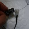
The components on board are marked "R", "D", and "C" (I assume, resistor, diode, capacitor). The micro-switch which controls the circuit is an Omron D2MC-5F (photo below).

Phil

P1020135.JPG
 

73's de Edd

Aug 21, 2015
3,622
Joined
Aug 21, 2015
Messages
3,622
That then makes all parts still available, and the probable need to get a lever style microswitch and then fabricate that piano wire portion / extension to then be soldered to the lever..
 

Minder

Apr 24, 2015
3,478
Joined
Apr 24, 2015
Messages
3,478
The lever is available by part No. CAA1M but may be a little short, .6mm piano wire can be used to make a custom length.
M.
 

Tha fios agaibh

Aug 11, 2014
2,252
Joined
Aug 11, 2014
Messages
2,252
I'd get some perf board and copy the layout of traces and components. Solid bell wire about 24 gauge works to simulate traces but obviously make thicker traces where necessary such as on Triac A1,A2 terminals.
 

mortier

Oct 9, 2017
4
Joined
Oct 9, 2017
Messages
4
Thanks. Could someone tell me a good place to order the components? Our Radio Shack is gone.

Phil
 

Minder

Apr 24, 2015
3,478
Joined
Apr 24, 2015
Messages
3,478
From Canada my goto is Digikey, but there are others such as Mouser and Jameco etc.
M.
 
Top