Maker Pro
Maker Pro

diy logic probe

foTONICS

Sep 30, 2011
332
Joined
Sep 30, 2011
Messages
332
I was working on my own logic probe design that met the following conditions:
1. run off 5V
2. Each logic level (high, low, inalid) will have its own LED
3. No LED should light if the probe does not touch anything

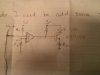
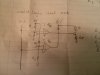
I have attached a few sketches that I drew up, I'm open to input and the only things to take note of is that I didn't use common resistor values just so I could quickly hammer out the math and I wasn't sure if the inputs to each of the comparators need current limiting resistors. The comparator is an open collector lm339
 

Attachments

  • logichigh.jpg
    logichigh.jpg
    107.7 KB · Views: 283
  • logiclow.jpg
    logiclow.jpg
    95.4 KB · Views: 333
  • invald.jpg
    invald.jpg
    105.3 KB · Views: 313

KrisBlueNZ

Sadly passed away in 2015
Nov 28, 2011
8,393
Joined
Nov 28, 2011
Messages
8,393
Hmm... I seem to recall a thread on this subject last year. It was started by... a user called... foTONICS!

Thread: https://www.electronicspoint.com/logic-probe-t248819.html
Post with my suggested diagram: https://www.electronicspoint.com/logic-probe-t248819.html#post1471120

The design I suggested in that thread does what you want except that it doesn't have a third LED for "invalid level". I've never seen that feature on a logic probe; normally, the fact that both LEDs are OFF can be taken to mean that the level is invalid. The probe is deliberately biased at an intermediate voltage, so when it's not touching anything, neither of the LEDs will light.

My design also uses CMOS levels (1/3 VCC and 2/3 VCC) rather than TTL levels; you would need to change the resistors that set the thresholds if you want TTL levels, and then it would only be usable at 5V.

Your design ideas are on the right track but the probe input is not biased, so it will not assume any particular voltage. When it's not touching anything, it will pick up noise and the probe's indication will be unpredictable.

The only way (well, probably not the only way, but the simplest way) to distinguish "invalid level" from "probe not connected" is to bias the probe at a voltage below 0V or above 5V. The monitoring circuit can then report "unconnected" if the probe is outside the 0~5V range, and "invalid level" if it's between the logic low and logic high thresholds.

This is not a good idea because it will inject current into the circuit being tested. It also requires a switched capacitor voltage generator or similar to generate the extra rail for bias.

Also, you've specified a green LED for high and (presumably) red for low; this is opposite to commercial logic probes.
 

foTONICS

Sep 30, 2011
332
Joined
Sep 30, 2011
Messages
332
Oh my I forgot about that thread. Judging by this new submission it looks like I've come a long way since then. I see your point about the invalid level, I was just designing the probe for more of an educational tool than actual lab equipment. Thanks again for the help.

On another note, why the probe input to the negative input as apposed to the positive?
 

KrisBlueNZ

Sadly passed away in 2015
Nov 28, 2011
8,393
Joined
Nov 28, 2011
Messages
8,393
I'm not sure what your question is. If you mean the connections to the inputs of the comparators, that is just the way they need to be wired so that each comparator output goes low in the appropriate state and lights the corresponding LED.
 

foTONICS

Sep 30, 2011
332
Joined
Sep 30, 2011
Messages
332
I guess my question was why sink instead of source, is it because this comparator can sink more current than it can source or is there a different reason?
 

KrisBlueNZ

Sadly passed away in 2015
Nov 28, 2011
8,393
Joined
Nov 28, 2011
Messages
8,393
You mean why are the LEDs connected from the outputs to VCC? Exactly why you said. The comparator outputs are open-collector, so they only sink current; they cannot source current. In other words, they close to ground when low, but when they're high, they do not pull to VCC. The load needs to be connected between the output and VCC.
 
Top