Maker Pro
Maker Pro

Distortion Pedal Redux

SparkyCal

Mar 11, 2020
849
Joined
Mar 11, 2020
Messages
849
I managed to find a ceramic capacitor at 100pF. It has the number 101 marked ion it. I hope that'a correct. I once tried to find a chart listing the cermanic capacitor numbers and their values, but it was hard to find. I once read something and understood how to decode the values, but I have long since forgotten.

I have not tried the adjusted build, yet, but here are my new numbers in volts.
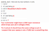
1. 1.44 V
2. .4.3 and falling
3. 4.40 V
4. 0 V
5. 1.0 V
6. .4.1 and falling
7. 9.3 V
8. 8.51 V

Not sure these readings are proper. Also, I am not sure I understand why Pins 2 and 6 show a number and then begin to fall in value.
 

SparkyCal

Mar 11, 2020
849
Joined
Mar 11, 2020
Messages
849
Still no sound. For the 10nF capacitor, I used a green film capacitor.Could that have caused a problem?
 

Audioguru

Sep 24, 2016
3,656
Joined
Sep 24, 2016
Messages
3,656
The circuit will not work when the resistor (220k) between pin 2 and pin 6 is missing. Is the resistor connected?
Where did you buy a fake TL081?

An Oriental 10nF green cap is marked 103.
 

Attachments

  • dist pedal redux again.png
    dist pedal redux again.png
    19.3 KB · Views: 6

SparkyCal

Mar 11, 2020
849
Joined
Mar 11, 2020
Messages
849
Hi AG

Yes, I did wire up the 220K between pins 2 and 6.

The green 10nF capacitor that I used is placed immediately when the guitar signal comes in.

I can try swapping ther Op amp with a 741. I believe they have the same pin maps. I can try that later and report in.

I can't explain why Pin 8 has voltage showing. it is not connected at all. But, if the op amp is not doing what we think it is, maybe that accounts for that anomaly too.
 

SparkyCal

Mar 11, 2020
849
Joined
Mar 11, 2020
Messages
849
I will try the 741cp later when I get a minute. I quickly measured the pins on the socket, without the op amp in.

Many of the measurements would not keep still. They seemed to be counting down into the negatives. Will take firmer measurements later and post them. If we take the op amp out of the equation and just measure the pins in the empty socket. will that tell us if it is the op amp?
 

Audioguru

Sep 24, 2016
3,656
Joined
Sep 24, 2016
Messages
3,656
Some 741 opamps do not work when the supply voltage is less than 10V. and some have an input resistance that is too low for this circuit.
A TL081 opamp has a 7V minimum supply and has an extremely high input resistance like an old vacuum tube.

Without the opamp in its socket, only pin 7 (9V from the battery) and pin 3 (4.4V from the voltage divider resistors) will have a voltage.
 

SparkyCal

Mar 11, 2020
849
Joined
Mar 11, 2020
Messages
849
Well AG and friends, we certainly cannot be faulted for lack of trying.

Tomorrow, I may try the 741 just to see what might happen, although based on your comment AG, it may fail simply on not enough voltage supply.

But I will report in once I try it.

On another, but related note, I am also venturing into a modular project. What I mean is this:

I am going to build three mini circuits.

The first will simply serve as the voltage divider
The second will begin at the guitar signal in, will travel through the op amp and will end at the Out
The third will be the diodes part.

I plan to make this modular by having plugs connect the three circuits together. For example, a plug carrying the lead from the 1M resistor from the voltage divider circuit, will be plugged into a receiving plug, that will carry it to pin 3 of the op amp circuit.

The reason why I'd like to do it this way, is it will enable me to isolate which part of the project is causing me issues.

As it stands now, each time I fail and do a rebuild, I am rebuilding the whole thing, including the voltage divider.

Having modular pieces will enable me too re- use the voltage divider for example. It will also enable me to swap out any of the three components to see what effect it will have on sound. For example, I may unplug the diodes circuit, and plug in a similar diodes circuit using different types of diodes.

Of course, this assumes I can successfully build this thing ;-)

Thoughts?
 

Audioguru

Sep 24, 2016
3,656
Joined
Sep 24, 2016
Messages
3,656
Modules for the simple opamp circuit will cause interference:
The 1M resistor and input of the opamp have very high input resistances that will pickup electricity 60Hz and all kinds of other interference unless careful shielding is used. The shielding will probably kill high audio frequencies.
Pin 2 of the opamp is also extremely sensitive to picking up interference which is why wiring to it from parts must have very short lengths.

It is a very simple circuit. Post photos of the wiring and maybe we will see the error.
 

SparkyCal

Mar 11, 2020
849
Joined
Mar 11, 2020
Messages
849
AG. I have built 90% of the modular thing. My goal,would be just to make sure the build works. If it does, I will build on a pcb and eliminate the noise issues. Or are you saying that the approach will fail outright and not produce sound even if it wired correctly?
 

Audioguru

Sep 24, 2016
3,656
Joined
Sep 24, 2016
Messages
3,656
The voltage divider has only 3 resistors and 2 or 3 capacitors so why can't it be near the opamp's pin 3? Your builds always had a correct voltage on pin 3.
The diodes should be connected directly to pin 2 with a short distance to pin 6.
A shielded cable from the diodes to a switch to turn them on and off will probably have enough capacitance to cause the opamp to oscillate at a high frequency.
 

SparkyCal

Mar 11, 2020
849
Joined
Mar 11, 2020
Messages
849
Well, the modular circuits work, but there is a catch.
They actually do produce sound, but it does not have much distortion in it. Unplugging the diodes does not seem to make a difference.If it does it is only slight.

I am thinking that it is due top what AG said- that the wires and stuff may degrade the circuit to the point where it will not function properly.

I also tried the previous circuit with the 741, and still, no sound whatsoever.

I am thinking I need to regroup. Maybe it is time to find a new circuit we could try? But it has to be rather simple.

I am open to ideas.

On a passive norte, we did get one of these circuit going on another thread- so there remains hope. I think used a 4558D on that one.
 

Audioguru

Sep 24, 2016
3,656
Joined
Sep 24, 2016
Messages
3,656
Does the opamp circuit work without the diodes? With its gain of 221 times then its output will have very loud severe clipping distortion.
Adding the diodes reduces the distorted level a lot and the distortion sounds different to the opamp clipping.
 

SparkyCal

Mar 11, 2020
849
Joined
Mar 11, 2020
Messages
849
AG: as I could not get the curcuit we were working on to work, I based the modular approach on the original schematic that it on this thread.
It is difficult to discern the sound, with all the noise. To me, it does not come across as loud or distorted. It almost sounds clean. But obviously, it passed through all the circuitry for the signal to come out and produce sound.
 

Audioguru

Sep 24, 2016
3,656
Joined
Sep 24, 2016
Messages
3,656
It is difficult to discern the sound, with all the noise. To me, it does not come across as loud or distorted.
Please describe the noise. Low frequency hum (from nearby electricity wiring), high frequency hiss, or audio from every radio and TV station and police and ambulance communications in town. Those are noise descriptions.
A say additional noises are electric guitar overdrive, acid rock and RAP. Oh yeah, Country Music is also noise.

The gain of 221 times is very high so the opamp output will be clipping like crazy. Maybe you think that overdrive clipping is normal and this extra gain is much worse?

Try adding the diodes which will reduce the output level 5 times preventing the opamp from clipping and the diodes will produce "soft" clipping.
 

SparkyCal

Mar 11, 2020
849
Joined
Mar 11, 2020
Messages
849
@AG More like a hiss that clobbers the signal.

Thanks Bertus for the link. I will check it out. In the interim., I am thinking:

Why don't I try following this video.


I know we have looked at this before, but because it is narrated, it could be a good way to find out what the heck I am doing wrong. We can follow the video, as I do the build, and see where it goes. ?

The full schematic is shown at 8:59. I think we've tried this before anyway- but maybe while following the video, may help.

P.S. I may be burning out and running. out of ideas.
 

Audioguru

Sep 24, 2016
3,656
Joined
Sep 24, 2016
Messages
3,656
The video has a very simple ordinary opamp circuit with a gain adjustment to produce a gain of 1 up to a gain of 501, soft clipping diodes, no bass (727Hz is at -3dB and lower frequencies at -6dB per octave) and reduced highs.
At 7:50 he talks about using a larger capacitor (that I recommended) producing a flatter bottom but it causes a fuzzy sound that maybe you do not like without having the diodes to soften the severe opamp clipping. Later he demonstrates using the tone control to turn down even more of the high frequencies distortion.
He mentions having a "sweet spot" in the middle of the frequency response which makes it sound like an old telephone with no bass and no treble sounds, just midrange sounds.

At 12:46 he demonstrates putting "the 0.022 capacitor" back in. Did he use 1/10th the original 0.22 capacitor by mistake that reduces the bass even more?
 

SparkyCal

Mar 11, 2020
849
Joined
Mar 11, 2020
Messages
849
I'm not sure AG. Good observations.

If you're willing, we can give this a try and see where we land.

Let me know.
 

SparkyCal

Mar 11, 2020
849
Joined
Mar 11, 2020
Messages
849
btw- I am thinking of using the 4558D for this because we have successfullybused it before, so I kn ow it works.

But I need a reminder der. I know that to silence the second op amp, you connect the second Out to the second - IN. (pins 6 and 7) , but do you also run the wire from the 1M resistor to Pin 5 , which is the Offset. If that's so, in effect, the 1M resistor lead will serve both Pin 3 and Pin 5 correct?

P.S. AG- I know you told me this before and posted a pic of it, I am recalling it from memory. I think I'm right, but wanted to double check.
 
Last edited:
Top