Maker Pro
Maker Pro

Display cabinet - PIR motion sensor & LED lights

Ronnie_Space

Jun 19, 2014
35
Joined
Jun 19, 2014
Messages
35
Hi Electronic Point Forum!

I am a designer by trade, but an electronic amateur, any help with this project would be highly appreciated and I will post back finished results/test for your interest.

I am making a clear display case for a model. I would like LED lights to activate when a viewer walks pass the display, and to stay on for a short amount of time say 10-15 secs.

I have the PIR Sensor HC-SR501 from ebay and it can be tuned to output a signal for the 10-15 second period I am looking for, the infra red range works perfect for my needs too.

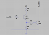
I rigged up the PIR with a transistor circuit (see diagram below - transistor 2N4401), which I was hoping would let me utilize the full 6V of the power source (6V is required for the PIR). This works in that I can run multiple LED's in parallel, however, the LED's are not quite as bright as I had hoped for.

I want to run the LED's at 3.2V 20mA, and therefore with a 6V battery used a 150 ohm resistor, this is fine in a simple test LED/battery circuit and I see 3.2V measured across the LED' with a multi-meter. However, putting them into the transistor circuit below I only measure 2.8V across the LED's, even if I remove the resistors before the LED's?


How can I get the LED's to run brighter (3.2V)?

I am also unsure if:

  • Does there need to be a resistor limiting the input to the Base of the transistor?
  • Have drawn/made the circuit in the correct manner?
  • Estimated battery life (using x4 AA Duracell coppertops in series for 6V)
diagram.jpg


Here is a video of the circuit with the light display set at a few seconds:


Any help much appreciated, as I am very close to getting this there!

Ronnie

PIR Sensor HC-SR50 Datasheet
http://www.mpja.com/download/31227sc.pdf

Transistor 2N4401 Datasheet
https://www.fairchildsemi.com/ds/2N/2N4401.pdf
 

Harald Kapp

Moderator
Moderator
Nov 17, 2011
13,722
Joined
Nov 17, 2011
Messages
13,722
Welcome aboard, Ronnie.

Your circuit lacks a base resistor limiting the current from the PIR sensor into the base of the transistor. With 10 LEds you'll end up with 200mA of collector current. At 200mA, DC current gain is approx. 100, which means base current needs to be at least 2mA. Add some safety margin and use 4mA of base current.

High output of the sensor is 3.3V (unfortunately it doesn't state at what current). Using Vbe=0.7V means a voltage drop of 2.6V across a base resistor, which at 4mA translates into Rb=2.6V/4mA=650Ohm. Use e.g. 649 or 680 from the E-series of resistors.
Ifthe PIR sensor is not able to supp´ly 4mA, you'll need an additional transistor to increase gain:
trans_amp-png.13638
 

Attachments

  • trans_amp.png
    trans_amp.png
    5.7 KB · Views: 1,601

Ronnie_Space

Jun 19, 2014
35
Joined
Jun 19, 2014
Messages
35
Thank you Harald for taking the time to reply. My electronics know-how is limited so I have been taking my time to understand your response and test results.

I am unsure what you mean by "Using Vbe=0.7V", specifically Vbe

But understood you used V=IR to find the resistor for the base of the transistor. I tried a 680 resistor (blue 5-band type) from the PIR output into the base of the transistor, but this made no difference to the brightness of the LED's or the voltage I measured across them (approx 2.7V).

To try your proposed circuit with two transistors, what value should I use for R1,R2,R3,R4?

Thanks for any help.

Below is what I tried based on your reply:

diagram%202.jpg


Best Regards

Barry
 

Harald Kapp

Moderator
Moderator
Nov 17, 2011
13,722
Joined
Nov 17, 2011
Messages
13,722
Barry,
Vbe is the Base-Emitter Voltage (Vce would be Collector emitter voltage etc.).

In my circuit, make:
R1= replace by a direct connection, no resistor required here.
R2=10kOhm...47kOhm, whatever you have at hand. this is not critical, any value in that range will turn on Q1
R3=680Ohm
R4=10kOhm...100kOhm, whatever you have at hand. This is not critical, just to ensure Q2 is off when Q1 is off.

By the way, what is the output votage of the PIR sensor in your 2nd circuit (with 680 Ohm to the base of he transistor)? What is the voltage across the 680 Ohm resistor? What is the voltage from collector to emitter of the transistor? Knowing these values could help identify the nature of the problem.
 

Arouse1973

Adam
Dec 18, 2013
5,178
Joined
Dec 18, 2013
Messages
5,178
Hi Harald
Just a question as I am intrigued. Why do you opt for R3 and no base resistor versus no R3 and a base resistor for Q2. What's the benefit?
Cheers
Adam
 

Harald Kapp

Moderator
Moderator
Nov 17, 2011
13,722
Joined
Nov 17, 2011
Messages
13,722
Theoretically bot ways are possible, you could even combine them.

But As seen from the input you have
Vin = 2*Vbe (for both transistors) + voltage across R2 + voltage across R1
You have Vinmax=3.3V and Vbe=0.6V (aaprox) which leaves you with
voltage across R2 + voltage across R1 = 3.3V-2*0.6V=2.1V
It's just a gut feeling of mine to use all this voltage to control current into Q1 via R2. I don't see a real techjnical reason.
 

Ronnie_Space

Jun 19, 2014
35
Joined
Jun 19, 2014
Messages
35
Hi Harald,

Again thanks for your reply, explanation and time, and also thanks Arouse1973 for your interest.

As requested, in my second circuit diagram:

The output voltage of the PIR sensor with 680 Ohm to the base of he transistor is 0.64V. The voltage across the 680 Ohm resistor is 0.73V.

If I measure the voltage from collector to emitter it is 6.2V when the PIR is inactive and 3.36V when active.

Does this help diagnose?

To confirm all I am looking to do is to make the LED's brighter. As they are when connected in parallel to a 6V supply running at 3.2V @20mA.

I will now make up the circuit as you suggested an report back..

Thanks

Ronnie
 

Harald Kapp

Moderator
Moderator
Nov 17, 2011
13,722
Joined
Nov 17, 2011
Messages
13,722
The output voltage of the PIR sensor with 680 Ohm to the base of he transistor is 0.64V. The voltage across the 680 Ohm resistor is 0.73V.
This is illogical. How can teh voltage across the resistor be higher than the output voltage of teh sensor? Did you by chance measure the base-emitter voltage instead?
Even is so, that is still not expected. The voltage across the base resistor and teh voltage from base to emitter of the transistor should add up to 3.3V, hat is the specified output voltage of teh sensor. Obviously the sensor's output doe not reach 3.3 V (as it should according to the datasheet).

With 0.73V across 680 Ohm you'll have a base current of 1mA. With a DC current gain of 100 the collector current (through the LEDs) is 100mA. Your 10 LEDs would like to see 200mA (as designed by you). The transistor will not be able to deliver this current from only 1 mA base current. Remove all but 1 LED and get the circuit operating, then add more LEDs.
 

Ronnie_Space

Jun 19, 2014
35
Joined
Jun 19, 2014
Messages
35
To further add, in case I have wired incorrectly, this was the prototype for the second circuit diagram I posted.


circuit%202%20-%20pic%201.JPG


circuit%202%20-%20pic%202.JPG
 

Harald Kapp

Moderator
Moderator
Nov 17, 2011
13,722
Joined
Nov 17, 2011
Messages
13,722
Please add labels to the wires so we can identify their function.
 

kpatz

Feb 24, 2014
334
Joined
Feb 24, 2014
Messages
334
My guess is the PIR sensor can only put out a small amount of current. Measure the voltage between the PIR output and ground (-) with it left open (disconnected from the transistor) and also with it connected. Does the voltage drop dramatically when it's supplying a current?

I found a datasheet for your PIR: http://www.mpja.com/download/31227sc.pdf

It shows an internal schematic and the output has a 1k resistor to limit the current, so the max current at 3.3V would be 3.3 mA, and there would be a corresponding voltage drop across that resistor.

I'd use 2 transistors in a Darlington configuration to increase the gain. Like this:
darl.png

Another option is to use an N channel MOSFET, but there aren't many that are fully on at Vgs under 3.3V. Most I've found are higher power ones that would be overkill in this circuit.
 

Ronnie_Space

Jun 19, 2014
35
Joined
Jun 19, 2014
Messages
35
This is illogical. How can teh voltage across the resistor be higher than the output voltage of teh sensor? Did you by chance measure the base-emitter voltage instead?
Even is so, that is still not expected. The voltage across the base resistor and teh voltage from base to emitter of the transistor should add up to 3.3V, hat is the specified output voltage of teh sensor. Obviously the sensor's output doe not reach 3.3 V (as it should according to the datasheet).

With 0.73V across 680 Ohm you'll have a base current of 1mA. With a DC current gain of 100 the collector current (through the LEDs) is 100mA. Your 10 LEDs would like to see 200mA (as designed by you). The transistor will not be able to deliver this current from only 1 mA base current. Remove all but 1 LED and get the circuit operating, then add more LEDs.


Apologies Harald, you're right that doesn't make sense. My lack of knowledge is showing here.

The voltage across the 680 ohm resistor is 0.73V.

I am not 100% sure how to measure the output voltage of the PIR sensor with 680 Ohm to the base of he transistor, can you please explain where to measure with voltmeter?

Ronnie
 

Ronnie_Space

Jun 19, 2014
35
Joined
Jun 19, 2014
Messages
35
My guess is the PIR sensor can only put out a small amount of current. Measure the voltage between the PIR output and ground (-) with it left open (disconnected from the transistor) and also with it connected. Does the voltage drop dramatically when it's supplying a current?

I found a datasheet for your PIR: http://www.mpja.com/download/31227sc.pdf

It shows an internal schematic and the output has a 1k resistor to limit the current, so the max current at 3.3V would be 3.3 mA, and there would be a corresponding voltage drop across that resistor.

I'd use 2 transistors in a Darlington configuration to increase the gain. Like this:
View attachment 13653

Another option is to use an N channel MOSFET, but there aren't many that are fully on at Vgs under 3.3V. Most I've found are higher power ones that would be overkill in this circuit.

Thanks kpatz for your reply,

voltage between the PIR output and ground (-) with it left open (disconnected from the transistor)

3.3V

voltage between the PIR output and ground (-) connected to the transistor

1.37V
 

Ronnie_Space

Jun 19, 2014
35
Joined
Jun 19, 2014
Messages
35
My guess is the PIR sensor can only put out a small amount of current. Measure the voltage between the PIR output and ground (-) with it left open (disconnected from the transistor) and also with it connected. Does the voltage drop dramatically when it's supplying a current?

I found a datasheet for your PIR: http://www.mpja.com/download/31227sc.pdf

It shows an internal schematic and the output has a 1k resistor to limit the current, so the max current at 3.3V would be 3.3 mA, and there would be a corresponding voltage drop across that resistor.

I'd use 2 transistors in a Darlington configuration to increase the gain. Like this:
View attachment 13653
.

This improved the brightness, testing with x1 LED the voltage measured across the LED was 3V, with x3 LED it was 2.8V, 2.8V & 2.9V for each LED. I need to get them brighter, at 3.2V

Ronnie.
 

BobK

Jan 5, 2010
7,682
Joined
Jan 5, 2010
Messages
7,682
Since the PIR sensor already has a 1K resistor on the output, eliminate the base resistor.

It would also help if you didn't have the emitter and collector reversed.

Bob
 

Ronnie_Space

Jun 19, 2014
35
Joined
Jun 19, 2014
Messages
35
Since the PIR sensor already has a 1K resistor on the output, eliminate the base resistor.

It would also help if you didn't have the emitter and collector reversed.

Bob

BINGO! yes... the transistor was the wrong way around...

I omitted the base resistor and reverted the the x1 transistor circuit and I am now measuring 3.2V across each LED.

Thanks Bob and kindly to ALL for their input. Apologies for my mistakes along the way.

Now, one more thing I would REALLY like to understand is; what is the predicted battery life if running constantly, or how many 10 second activations could this circuit provide with x4 duracell AA batteries wired up as 6V.

Ronnie
 

kpatz

Feb 24, 2014
334
Joined
Feb 24, 2014
Messages
334
Measure the current draw of the circuit when idle (LEDs off) and again with them illuminated with fresh batteries. Based on that we can estimate the lifespan of a set of AAs (average around 2000 mAH for a set of alkalines)

Another factor to consider is the voltage of the batteries will drop as they wear down, so you may only be getting 4.5V from the cells when they're weak. There may be a point where the PIR will stop working or the LEDs will be too dim to be useful.

Larger batteries will last longer, so if you can use C or D instead of AA you'll go longer on a set. A set of NiMH rechargeables is an option too, but note their nominal voltage is lower, around 1.2V per cell so you may need to use 5 or 6 instead of 4. An advantage of rechargeables is their voltage curve is much flatter; their voltage doesn't drop much until the cells are almost fully discharged. This will give a more consistent brightness over time than alkalines will. And you can recharge them again and again.

Lastly, experiment with different resistor values for the LEDs. LEDs tend to lose efficiency at higher currents, so for example driving an LED at 30 mA instead of 20 mA won't make it 50% brighter. You might find that a lower current is sufficiently bright, or you might find you don't need 10 LEDs, but five are sufficient. The less current you use, the longer the batteries will last.

Look for high-efficiency white LEDs too. I've seen ones in flashlights that are blindingly bright. I don't know how much current they draw, but LED flashlights usually go pretty far on a set of batteries.
 
Last edited:

(*steve*)

¡sǝpodᴉʇuɐ ǝɥʇ ɹɐǝɥd
Moderator
Jan 21, 2010
25,510
Joined
Jan 21, 2010
Messages
25,510
I'm coming in a bit late on this one, but a good way to connect devices like this PIR to your breadboard are cables like this.

No real functional difference, it just makes the process even more "solderless".
 

Ronnie_Space

Jun 19, 2014
35
Joined
Jun 19, 2014
Messages
35
Measure the current draw of the circuit when idle (LEDs off) and again with them illuminated with fresh batteries. Based on that we can estimate the lifespan of a set of AAs (average around 2000 mAH for a set of alkalines)

Another factor to consider is the voltage of the batteries will drop as they wear down, so you may only be getting 4.5V from the cells when they're weak. There may be a point where the PIR will stop working or the LEDs will be too dim to be useful.

Larger batteries will last longer, so if you can use C or D instead of AA you'll go longer on a set. A set of NiMH rechargeables is an option too, but note their nominal voltage is lower, around 1.2V per cell so you may need to use 5 or 6 instead of 4. An advantage of rechargeables is their voltage curve is much flatter; their voltage doesn't drop much until the cells are almost fully discharged. This will give a more consistent brightness over time than alkalines will. And you can recharge them again and again.

Lastly, experiment with different resistor values for the LEDs. LEDs tend to lose efficiency at higher currents, so for example driving an LED at 30 mA instead of 20 mA won't make it 50% brighter. You might find that a lower current is sufficiently bright, or you might find you don't need 10 LEDs, but five are sufficient. The less current you use, the longer the batteries will last.

Look for high-efficiency white LEDs too. I've seen ones in flashlights that are blindingly bright. I don't know how much current they draw, but LED flashlights usually go pretty far on a set of batteries.

Thanks for the reply kpatz.

Please see video below measuring the current draw of the circuit when idle and illuminated. I current have only x6 LED's in series, the final circuit will have x10. The multi-meter reads 0A current draw when idle and 80mA(?) when illuminated. I must admit reading the multi-meter on the current setting confuses me somewhat..!


These LED's are rated at IF max 30mA and VF max 3.8V. They are currently set to run at 20mA @ 3.2V. I may choose some higher quality, wider angle LED's for the final display, but running at the same spec.

LED details:

http://www.ebay.co.uk/itm/Ultra-Bri...plies_ET&var=590073581283&hash=item43b142aace

Batteries are x4 1.5V AA Duracell copper tops, wired in series for 6V.

I am wondering if I can use x3 AA Duracell for 4.5V with the SAME battery life and SAME brightness, as I have noticed whilst the spec of the PIR 5V to 20V, the spec also details a working range of "4.5V to 20V". I have several displays to make, so the less cost the better.

PIR Sensor HC-SR50 Datasheet
http://www.mpja.com/download/31227sc.pdf

All help much appreciated. Really please I joint this forum.

Ronnie
 
Top