73's de Edd
- Aug 21, 2015
- 3,622
- Joined
- Aug 21, 2015
- Messages
- 3,622
Sir Alektron . . . .et al . . .
Why not figure out where you are going to source the new diode from and check their solder offerings and we can comment upon the possibilities that they offer.
It's absolutely normal for me to scavenge 70-80's vintage " free " electronics boards to harvest components AND also use downward gravity to to get ALL their solder and tap on the lid of a small jar with a 1 inch hole in it.
Water is in the glass and the small solder drops form on the way down. With time, I must have accumulated 12 of the largest orange pill containers, crammed full with them. . . . them being a bit weighty also.
Just pick one droplet of the size needed for your joint and then have a drop of liquid rosin flux and a Stainless Steel tweezer set applies the solder drop in place and then you solder . . . . all for FREE.
( My flux even comes from my pine trees sap + denatured alcohol used as its solvent.)
I have mostly used ?(Brain fart) and their inner "44" rosin core or Ersin Multicore solder, and of a sizing either 1 or two gauges down smaller in size from what you showed us. 60 tin 40 lead or sometimes PWICEY PWEMIUM BWEWED 67/33 blend . . . . . with even a bit of silver bearing stashed away.
FAILURE ANALYSIS . . .
As it was , with that +VCC being pulled down, and you not finding Q8 dead shorted from C-E, and a 22 ohm resistance presence was being found on our +5VDC Bee supply line.
I just needed Q8 completely out of circuit to be sure that the unit was not avalanching from C-E and acting like a power zener after it had a voltage presence upon it.
With it out of circuit . . . . then the circuitry to he left of Q8 and the right of Q8 was isolated . . .and the problem was being on the right half of it.
HOWEVER, I wasn't expecting a 22 ohm reading of the diode, usually they either open circuit or dead short.
THAT then accounted for the 22 ohms as then NOT being a load on the +5VDC Bee supply line as I was suspecting, which could only account for an ~ 250 ma loading on the supply .
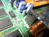
BUT with no diode there it could not rectify the ringing of the toroid inductor and collect its energy in the 1000ufd /6v storage / filtering capacitor.
Didn't know that you had the ESR + meter . . . . usually I am having to work with people that are so piss pot poor . . . .equipment wise . . . . that we have to find innovative / cutting edge work arounds with Scotch tape , toothpicks and split clarinet reeds . . . . along with a liberal sprinkling of flooby dust.
How about a testing of those 4 E caps between the Super cap and the toroid area. Most of my suspicion is directed at the 1000 unit as it could have been instrumental in the diode failure, by gradual time driven overheating of the diode. ( And that might account for the diodes abnormal failure mode.)
Looks like that KLEIN that you now have is fully encroaching upon being a FLUKE wannabe.
73's de Edd
.....
Why not figure out where you are going to source the new diode from and check their solder offerings and we can comment upon the possibilities that they offer.
It's absolutely normal for me to scavenge 70-80's vintage " free " electronics boards to harvest components AND also use downward gravity to to get ALL their solder and tap on the lid of a small jar with a 1 inch hole in it.
Water is in the glass and the small solder drops form on the way down. With time, I must have accumulated 12 of the largest orange pill containers, crammed full with them. . . . them being a bit weighty also.
Just pick one droplet of the size needed for your joint and then have a drop of liquid rosin flux and a Stainless Steel tweezer set applies the solder drop in place and then you solder . . . . all for FREE.
( My flux even comes from my pine trees sap + denatured alcohol used as its solvent.)
I have mostly used ?(Brain fart) and their inner "44" rosin core or Ersin Multicore solder, and of a sizing either 1 or two gauges down smaller in size from what you showed us. 60 tin 40 lead or sometimes PWICEY PWEMIUM BWEWED 67/33 blend . . . . . with even a bit of silver bearing stashed away.
FAILURE ANALYSIS . . .
As it was , with that +VCC being pulled down, and you not finding Q8 dead shorted from C-E, and a 22 ohm resistance presence was being found on our +5VDC Bee supply line.
I just needed Q8 completely out of circuit to be sure that the unit was not avalanching from C-E and acting like a power zener after it had a voltage presence upon it.
With it out of circuit . . . . then the circuitry to he left of Q8 and the right of Q8 was isolated . . .and the problem was being on the right half of it.
HOWEVER, I wasn't expecting a 22 ohm reading of the diode, usually they either open circuit or dead short.
THAT then accounted for the 22 ohms as then NOT being a load on the +5VDC Bee supply line as I was suspecting, which could only account for an ~ 250 ma loading on the supply .
BUT with no diode there it could not rectify the ringing of the toroid inductor and collect its energy in the 1000ufd /6v storage / filtering capacitor.
Didn't know that you had the ESR + meter . . . . usually I am having to work with people that are so piss pot poor . . . .equipment wise . . . . that we have to find innovative / cutting edge work arounds with Scotch tape , toothpicks and split clarinet reeds . . . . along with a liberal sprinkling of flooby dust.
How about a testing of those 4 E caps between the Super cap and the toroid area. Most of my suspicion is directed at the 1000 unit as it could have been instrumental in the diode failure, by gradual time driven overheating of the diode. ( And that might account for the diodes abnormal failure mode.)
Looks like that KLEIN that you now have is fully encroaching upon being a FLUKE wannabe.
73's de Edd
.....
Last edited:
")


