Gaupa95 submitted a new Showcase Item:
Desktop Case lights using WS2812B Leds.
Read more about this showcase item here...
Desktop Case lights using WS2812B Leds.
Hi this is my first project log on this site. I will be updating as I find time.
A few months back I bought some WS2812B led strips off ebay to play with but I haven't gotten around to working with them before now.
The microcontrollers I had around was some PIC18f14k50.
So what I first tried was the method of using fast clocked Spi to emulate the 1-wire protocol for the ws2812 leds. but it ended in failure and I could not get any consistent data transfer.
So I found a document from Microchip which explains how to use the CLC module they have on some of their PIC16f chips to interface with WS2811 led drivers.
link : http://ww1.microchip.com/downloads/en/AppNotes/00001606A.pdf
this document gave me an idea about how to create some custom external logic to fit the protocol.
After reading the document I figured out logically what I would have out would be:
Q = ( !SDO&CLK&PWM ) || ( SDO&CLK )
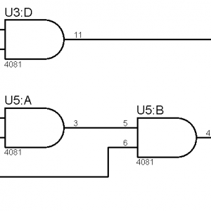
So my first attemt I build a circuit that did this with only logic gates:
View attachment 19493
And this seemed to work pretty good when I got the uC to run with some code and adjusted the PWM. But I figured out that it was a waste to have 3 IC's to do all this so I figured out I'd use some transistor logic instead to do some of the functions.
After a bit in thinking and simulating I had this circuit instead:
View attachment 19492
By switching out the inverter and OR gate I saved a lot of space.
The reason I did make a darlington connection at the end was due to the "or" gate being slow. I figure I could just have decreased the value on R6. but it works so I suppose it's fine.
Now I've been working on the program.
in my first prototype I was running it on a 48Mhz crystal. (well that was what I though)
But I figured out later that the PIC couldn't drive that kind of crystals and was only running at 20-30Mhz or somthing like that. not sure how to properly mesure that so I figured out I'd use the internal oscillator.
The PIC has the option to run it's internal 8Mhz osc though PLL I could gain a fairly stable 32Mhz cpu clock.
Since the CPU's arcitecture uses 4 clock pulses each instruction we can consider that a stable 12Mhz for all the internal pereferials.
This means that the internal instruction clock runs at 12Mhz. And that's where timers get their clock.
To drive the MSSP module I use the option of TMR2 / 2. this mean it will clock out a bit every secound time timer 2 resets.
Timer 2 is also the timer which generates the...
Read more about this showcase item here...
Last edited by a moderator: