Congratulations
")
First of all, thanks so much KrisBlueNZ for the quick diagnosis and very helpful instructions!
You're welcome
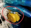
The resistor is truly a resistor as you mentioned, and it's actually the irregular 8.5Ω. The way I confirmed is I pulled the same resistor out of my 2nd dehumidifier (same make/model, which coincidentally also flaked out as well couple days ago, but appears to be for a different power board related reason) and checked the resistance (as you showed me). It showed 8.5.
What does the multimeter display on ohms range when you short the probes together? They don't normally display 0.0Ω. If it displays 1.0Ω when you short the probes together, then it always indicates 1Ω higher than the true resistance, so in that case, the resistor would be 7.5Ω.
Of course it is possible that it's 8.5Ω but I kind of doubt it.
If you don't mind, I am very curious in how you immediately suspected RF1 as bad. Obviously, I'd like to learn as much about this as I've sort of struggled with it for the past few weeks. What clued you in on the bad resistor? As opposed to bad relay, diode, capacitor, etc...
Have a look at this schematic diagram. It's from an example circuit design in a document coded DER-227 on the Power Integrations web site, at
http://ac-dc.power.com/design-support/reference-designs/design-examples/der-227-3-w-single-output/. It uses the LNK363, not the LNK364 that's used on your board, but they're very similar. And the circuit design also looks very similar, even down to the reference, RF1, for the fusible resistor! This power supply is called a "current mode flyback" circuit.

On your board, the phase line from the mains supply goes through the glass fuse, then straight to RF1. The other side of RF1 connects to the bridge rectifier formed by D1~4. The output of the bridge rectifier goes to the first smoothing capacitor, then through an inductor (they replaced the other inductor with a bit of wire to save money) to the second smoothing capacitor (incorrectly labelled as a second C1 in that diagram), then to the primary circuit, which consists of the primary winding of the transformer and the Power Integrations LNK363 or LNK364 controller IC.
When the circuit is working normally, the mains supply is converted into a DC voltage across those capacitors, and the controller IC switches ON and OFF rapidly, sending pulses of current into the primary of the transformer. These pulses appear at the secondary, where they are rectified by a diode (D5 on the diagram above; D6 on your board) and smoothed, and become the power supply's output voltage.
The components connected across the primary of the transformer are suppression components; they're there to limit the voltage that the control IC is subjected to when it turns OFF. They don't often fail but it's worth checking whether the diodes are short.
Switching supplies like this often fail because of a voltage surge on the incoming mains supply. The voltage across the smoothing capacitors increases, subjecting the controller IC to a voltage that's too high for it to handle, and the internal MOSFET switching device inside the controller IC overheats and goes short circuit. This may cause a visible sign such as a crack or pit in the IC.
When the controller IC goes short circuit, the transformer primary becomes connected straight across the smoothing capacitors, and they discharge quickly. The mains supply is still present, and a heavy current flows in RF1 and the bridge rectifier diodes D1~4. This causes RF1 to dissipate a lot of power, and it fails very quickly - that's what a fusible resistor does. This all happens much too quickly to affect the glass fuse.
I knew from your description that the controller IC had failed (when they fail, they almost always fail short) and that you had replaced it. So I asked you to check RF1, which I assumed would be open circuit, since that's the way things usually go. I also asked you to check the bridge rectifier diodes, because they were subjected to a brief burst of high current when the controller IC and RF1 failed, and the output rectifier diode just in case it had been damaged by the surge (these don't often fail).
Now, my follow up challenge is to fix the 2nd unit. It also doesn't power up. Obviously I'll need to source another 8.5Ω solution (thanks btw for the links!). I'll also perform the same checks on the diodes and do a full check if there are visible issues. On that unit, i noticed a small ticking sound when powered up...not sure if this helps with the diagnosis.
Yes it does. That ticking sound is called hiccuping, and it means that the controller IC is trying to start up, but it is detecting a problem and shutting down. This shutting down is very quick and causes the tick sound. Then it tries to start up again, detects the same problem, and shuts down. And it repeats.
There's no problem with RF1, the bridge rectifier, or the controller IC - at least, it hasn't failed short. The problem could be an overload at the output, or a failed component in the suppression circuit at the primary. So check D6 for short circuit, and D5 as well. You don't need to lift them out of circuit. D5 is on the underside. Let me know what the markings are on D5 and D6 as well.
Also have a close look at the output smoothing capacitors - the two blue ones between the transformer and the output connectors. Make sure the tops and bottoms are flat with no sign of bulging or stretching of the plastic sleeves.
If you don't find any problems, we can start making some measurements.
It's also quite suspicious that the two units flaked out within 3 months of each other, after having been used for the past 5 years. My wife jokingly mentioned the manufacturers set some sort of timers to commit suicide in order for us to throw away and waste money buying new ones.
Sometimes the manufacturers cut corners with the design to save a few cents - an example is the inductor that they replaced with a piece of wire. Sometimes the components don't meet their claimed specifications. This is common with electrolytic capacitors (E1 and E2 in the primary circuit, and the two blue output capacitors) made by various Chinese electrolytic manufacturers, and was the cause of the "bad capacitor plague" that affected computer motherboards around the middle of last decade. Component counterfeiting is also a significant problem, so even components from apparently good brands may not be what they seem!