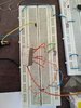
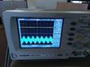
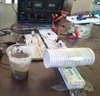
I used sbl-1 mixer for decreasing signal frequency from 3.174 MHz to 10 kHz. The generated signal has high noise level. The butterworth and sallen-key filter was used to eliminate noise, nevertheless there is the noise. There is also the possibility of sending images of the circuit. How can i eliminate the noise?
Please help me.
Thank you
Please help me.
Thank you