Maker Pro
Maker Pro

Dead Automatic Battery Charger for Autos. Please help me troubleshoot.

KrisBlueNZ

Sadly passed away in 2015
Nov 28, 2011
8,393
Joined
Nov 28, 2011
Messages
8,393
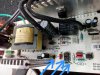
The micro on the control board senses the battery voltage directly across the fat wires that go to the battery clamps. But if the relay is damaged, the controller could ramp the power supply up to maximum output voltage and still not be able to charge the battery.

The power supply must be running because the control board is powered from a separate tap on the secondary of the main transformer. But that doesn't mean that the charging output from the power supply is necessarily working properly.

The charger output voltage appears across the 2200 µF 25V electrolytic, then goes through the relay contact and directly to the battery. There is no current shunt on the power board; current must be sensed somewhere else, if at all.
 

Rioriorio

Nov 20, 2014
15
Joined
Nov 20, 2014
Messages
15
1. The capacitor you replaced should have been a low ESR type. Is that what you used? Do you still have the original? You said it's 2200 µF, 25V, but can you list ALL of the markings on it?

2. TR1 is very unlikely to be the problem. When the main switching MOSFET in a switching power supply fails, it usually fails short and th fuse blows.

3. The measurements you got for D5 are normal; the voltage is low because it's a Schottky diode, not a standard diode.

4. You could check the components in the discoloured area to the left of the big transformer. These are the suppression components and if there's a problem there, it could restrict the output voltage I guess.

5. Can you take another photo of the top side of the power board with the wires pulled away so we can see what's behind them? Also, if possible, take the photo from further away, using a zoom lens, so the tall components don't block out so much of the parts that are next to them. Take the photo at exactly 90° to the board, pointing at the exact centre.

6. What type of batteries have you tried to charge? How many of each type? Were they in known good condition?

7. How does the charge percentage display behave? Does it count steadily to 100% and does the charger stop when it reaches 100%? Does the charger continue after 100% is reached? Is it supposed to?

8. There are several reviews at http://www.amazon.com/Schumacher-SSC-1500A-CA-SpeedCharge-Charger-Battery/product-reviews/B000H961YI that mention that the charge state indication hits 100% before the battery is fully charged.

9. Can you confirm that the only connection to the control board is the five wires at the top right corner that connect to "J1"?

10. (For future reference, the wires on this connector are: 0V; circuitry +ve supply from U4; relay control; battery voltage; output voltage control to optocoupler.)

11. That charger doesn't appear to have any way to measure the actual charge current. Unless there is something attached to the fat wires that run from the power board to the battery clamps.

Edit: Yes, debe's suggestion of possible damage to the relay is worth checking out as well. While the unit is trying to charge a battery, but the displayed voltage is low, measure the DC voltage across the relay contact. It should be very low - less than 0.01V. If it's higher, you need to replace the relay.

1. Two pictures of the old/bad capacitor:
2014-11-21 10.55.33.jpg 2014-11-21 10.55.47.jpg
Link to new capacitor: http://www.newark.com/nte-electronics/nev2200m25fh/capacitor-alum-elec-2200uf-25v/dp/34P1071

5. I tried to take some better pictures. How are these? Need me to zoom in on any area in particular?
2014-11-21 11.25.08.jpg 2014-11-21 11.25.32.jpg 2014-11-21 11.25.48.jpg

6. 12 v car batteries. 3 of them. 2 were auto batteries and one was a big 12v for autoscrubbers. They were in known good condition. Lights and stuff were left on in the car batteries requiring a recharge.

7. The percentage display starts at what percentage charged the battery is say 35%. It then slowly moves up to 100% and then the charger stays lit, but stops charging. I believe this is what it is supposed to do. Once it reaches 100%, the charging led turns off and the green charged led comes on.

9. Yes, the only connection to the controls is the 5 pin connector (I see it as J2. Is that what you meant?). There is a 2 pin connector to the left of J2 which is a small fan connection.

Testing the relay:

This is a diagram of the relay that I pulled from the internet:
Relay Pic.jpg

When you say test the voltage across the relay contact, do you mean from the middle pin in the left to the top pin on the right?

If so here are the multimeter readings when the clips are connected to a 12v battery with the plug connected to 110v AC. It says it's charging.

On the 2 amp setting: 7.70 v
On the 10 amp setting: 7.78 v
On the 15 amp setting: Started at around 7.95 then dropped and stabilized at 7.56.

For what it's worth, the digital readout on the charger had these readings at the different amp levels:

2 amp: 12.3 v
10 amp: 12.1 v
15 amp: 11.7 v
 

KrisBlueNZ

Sadly passed away in 2015
Nov 28, 2011
8,393
Joined
Nov 28, 2011
Messages
8,393
OK, the original one claims to be low-ESR but it's a cheap Chinese type with no publically accessible data sheet, and probably was never much good. The replacement isn't a low-ESR type at all. It will probably work but it will go the same way that the original one did, possibly even more quickly. A suitable replacement would be http://www.digikey.com/product-detail/en/EGPA250ELL222MK30S/565-3377-ND/3528510.
5. I tried to take some better pictures. How are these? Need me to zoom in on any area in particular?
No, those are great. You're very forthcoming with information. It makes it easy to work with you.
6. 12 v car batteries. 3 of them. 2 were auto batteries and one was a big 12v for autoscrubbers. They were in known good condition. Lights and stuff were left on in the car batteries requiring a recharge.
OK.
7. The percentage display starts at what percentage charged the battery is say 35%. It then slowly moves up to 100% and then the charger stays lit, but stops charging. I believe this is what it is supposed to do. Once it reaches 100%, the charging led turns off and the green charged led comes on.
9. Yes, the only connection to the controls is the 5 pin connector (I see it as J2. Is that what you meant?). There is a 2 pin connector to the left of J2 which is a small fan connection.
Yes. Well, it appears that the charger doesn't actually monitor the charge current; it must estimate it based on some nominal internal resistance for the battery.
Testing the relay:
When you say test the voltage across the relay contact, do you mean from the middle pin in the left to the top pin on the right?
Yes.
If so here are the multimeter readings when the clips are connected to a 12v battery with the plug connected to 110v AC. It says it's charging.
On the 2 amp setting: 7.70 v
On the 10 amp setting: 7.78 v
On the 15 amp setting: Started at around 7.95 then dropped and stabilized at 7.56.
OK, it seems that the relay is not closing. Either it's faulty internally, or it's not being energised.

Here's a marked-up view of the track side.

epoint 271428 annotated.jpg

The 0V point is the main 0V rail for the whole charger. Connect your multimeter black probe there when measuring voltages.

PSO is the main output from the power supply that charges the battery. RC+ is the positive supply for the relay coil, and it appears to be connected directly to PSO via a jumper that's buried between the relay and the electrolytic that you replaced. Can you confirm that it's just a jumper in there? It's partly covered by grey goop.

The relay contact should connect between PSO and the fat red wire that goes to the battery. Can you confirm this? It seems pretty clear from the photo but I want to make sure there's nothing in between them.

So the voltages that you measured were between PSO and the battery positive? That means the contact wasn't closing.

In that case I need you to measure the voltages at RC+ (which should be the same as PSO) and the point marked C.

The voltage at C should be less than 0.5V and RC+ should be at least 12V while the charger is operating. If that's true, there is voltage across the relay coil but its contacts aren't closing, so it's faulty.

If the voltage at C is about the same as RC+ then the driver transistor isn't turning ON. Measure the voltage at B and let me know.

Of course, keep well clear of the live end of the board while you're doing these measurements! Also, the circuitry above the "UNR" marking is live too. You sound like a sensible guy and I think you'll be OK but if you're unsure, ASK!
 

Rioriorio

Nov 20, 2014
15
Joined
Nov 20, 2014
Messages
15
The 0V point is the main 0V rail for the whole charger. Connect your multimeter black probe there when measuring voltages.

PSO is the main output from the power supply that charges the battery. RC+ is the positive supply for the relay coil, and it appears to be connected directly to PSO via a jumper that's buried between the relay and the electrolytic that you replaced. Can you confirm that it's just a jumper in there? It's partly covered by grey goop.

Yes, it is a jumper

The relay contact should connect between PSO and the fat red wire that goes to the battery. Can you confirm this? It seems pretty clear from the photo but I want to make sure there's nothing in between them.

Yes, this is true.

So the voltages that you measured were between PSO and the battery positive?

Yes.

In that case I need you to measure the voltages at RC+ (which should be the same as PSO) and the point marked C.

The voltage at C should be less than 0.5V and RC+ should be at least 12V while the charger is operating. If that's true, there is voltage across the relay coil but its contacts aren't closing, so it's faulty.

If the voltage at C is about the same as RC+ then the driver transistor isn't turning ON. Measure the voltage at B and let me know.

These are the voltages I measured all on the 15 amp setting.

0V to PSO 19.42V
0V to RC+ 19.5V
0V to C 11.6V
0V to B 10.1V

I measured these and during my measurements something on the board started whining and the capacitor I just replaced popped loudly and burst.
 
Last edited:

KrisBlueNZ

Sadly passed away in 2015
Nov 28, 2011
8,393
Joined
Nov 28, 2011
Messages
8,393
Oh dear!

You'd better re-check the Schottky double diode on the heatsink, as well as replacing the electrolytic again.

Those voltages you measured on the transistor are not what I was expecting. Can you push the transistor over againt the board so its flat face is visible, and take a photo from above, including the relay.
 

Rioriorio

Nov 20, 2014
15
Joined
Nov 20, 2014
Messages
15
Ok, sorry it took a few days.

I've replaced the capacitor.

The schottky double diode has the same readings as before.

This is the best picture of the transistor and relay that I could get.

2014-11-25 12.28.28.jpg

There's what I think is a diode that looks like it got hot and a little burned. It reads 263 one way and goes to 1 like it should the other.

This is what it looks like:
2014-11-25 12.41.05.jpg

UPDATE...A couple hours later...

I checked another diode on the board and it appears to be bad. It reads about the same both ways. I'm unsure if I checked this one before, but this is the one (directly to the right of the red battery wire):

2014-11-25 13.38.36.jpg
 
Last edited:

KrisBlueNZ

Sadly passed away in 2015
Nov 28, 2011
8,393
Joined
Nov 28, 2011
Messages
8,393
OK, the transistor is connected the way I thought it was connected. It seems like the transistor is faulty or damaged, and it isn't activating the relay.

It looks like Radio Shack have the transistor: http://www.radioshack.com/2n4401-npn-switching-transistor/2762058.html but it's not an uncommon type and might be available from a local electronics component shop, if you know of one. Otherwise Digi-Key have it, of course.

Is it the orange and black glass diode you're concerned about? It just regulates the voltage to the fan, so if the fan is working, and running at a constant speed, don't worry about that diode.
 

Rioriorio

Nov 20, 2014
15
Joined
Nov 20, 2014
Messages
15
Ok, do you think the relay is OK?

I'll check to see if Radio Shack has one here locally. It is on my way home from work.

Did you see my update to my previous post?

I said:

UPDATE...A couple hours later...

I checked another diode on the board and it appears to be bad. It reads about the same both ways. I'm unsure if I checked this one before, but this is the one (directly to the right of the red battery wire):

2014-11-25 13.38.36.jpg
 

KrisBlueNZ

Sadly passed away in 2015
Nov 28, 2011
8,393
Joined
Nov 28, 2011
Messages
8,393
Ok, do you think the relay is OK?
Can't say at the moment. It might be worth replacing it with a better quality one anyway.
I'll check to see if Radio Shack has one here locally. It is on my way home from work.
OK.
Did you see my update to my previous post?
No I hadn't seen it. Did you measure that diode in circuit or out of circuit? It's connected straight across the relay coil, so it won't measure properly in circuit. You'll have to lift one end. Then, if it still measures funny, replace it. A 1N400x (4001~4007) will be suitable.
 

Rioriorio

Nov 20, 2014
15
Joined
Nov 20, 2014
Messages
15
Ok, good news. The Radio Shack has that transistor in stock. I'll get it on the way home.

I measured that diode out of circuit and it seems to be fine.

I'll let you know what happens after I switch out the transistor.

Can you recommend a better relay?

Thanks.
 

Gryd3

Jun 25, 2014
4,098
Joined
Jun 25, 2014
Messages
4,098
At this stage I would recommend "If it's not broken, don't fix it". You'll just be making life harder for yourself.
Op was told it may be worth replacing anyway, conflicting advice can fluster people.

Take a little from both replies. There is no proof the existing one is damaged, so it may not be worth the extra effort to specifically remove it just to 'upgrade' it if it currently works fine.
If you plan to remove it anyway to test it, or if you have a good reason to suspect it will die soon, then it would be worth swapping out to prevent having to take apart the unit again in the near future.

Of course, once you swap the transistor out, you will have a better understanding of whether or not a replacement is required, so in either case, it may be better to wait.
 

(*steve*)

¡sǝpodᴉʇuɐ ǝɥʇ ɹɐǝɥd
Moderator
Jan 21, 2010
25,510
Joined
Jan 21, 2010
Messages
25,510
Op was told it may be worth replacing anyway, conflicting advice can fluster people.

Yeah, that's replacing it. That's fine. But I'd be looking for the same relay (i.e. same manufacturer and series etc.).

Looking for a "better" one might just add some more variables to the problem that's being fixed.

I suggest the OP wants a "suitable replacement" rather than a "better relay".
 

KrisBlueNZ

Sadly passed away in 2015
Nov 28, 2011
8,393
Joined
Nov 28, 2011
Messages
8,393
I disagree in this case, because the original relay, in this case, is a "SANYOU" brand! In my experience, Chinese look-alike names are a sign of low quality ("Transonic" TV sets, anyone? How about "Technical Pro" audio gear?) and in any case, the charger is apparently rated for a maximum charging current of 15A, which is the claimed limit on the carrying current of that relay.

Digi-Key is having a problem with their product selection system but I found this one at Mouser: http://uk.mouser.com/ProductDetail/...GAEpiMZZMtGt%2bn33CgIP6qiYKfprhIZuLt1qQ3JmdY=
 

Rioriorio

Nov 20, 2014
15
Joined
Nov 20, 2014
Messages
15
UPDATE:

Just wanted to update you all and sincerely thank you for your help. I replaced the transistor referenced above as well as a diode that I found that was fried. It worked for about 5 minutes then started to smell like it was burning.

Then I found out this Schumacher charger has a 5 year warranty so I returned it and they sent a brand new (might be refurbished) one. I thought it was only a year warranty which was far past, but I called and they said to send it back.

Again, I really want to thank you all for your help.
 

Demetric

Sep 27, 2015
1
Joined
Sep 27, 2015
Messages
1
Model: Schumacher SSC-1500A It has 3 power settings, 2 amps, 6 amps, and 15 amps

Symptoms: Not fully charging batteries anymore. It will still partially charge batteries, but not all the way.
The charger turns on and the display turns on also.

I opened up the case and there was a capacitor bulged so I replaced it, but the charger still doesn't work. I replaced the one on the second picture right next to the big red/black cable.

I do have an esr capacitor meter and I'll have to check to see if my multimeters at home have a diode setting.

I'm including pictures of the circuit boards.

Attached to the heat sinks (assuming they're heat sinks, the tall long metal pieces) are what appear to be transistors)

Could someone please help me figure out what's wrong with this so I can fix it?

This first picture is of the circuit board on the display. The other pictures of circuit boards are of the main one inside.
View attachment 17128 View attachment 17129 View attachment 17130 View attachment 17131 View attachment 17132 .


Thanks.
Can i just buy a replacement board?
 

wilfran420

Oct 9, 2018
1
Joined
Oct 9, 2018
Messages
1
Thanks.[/QUOTE]

Hello I have a similar problem. You can help? the damaged resitances and the integrated circuit u1 I do not have their references. You could send me the reference of U1 and values of these resistances.
 

Attachments

  • tarjeta cargador.jpg
    tarjeta cargador.jpg
    205.7 KB · Views: 6

davenn

Moderator
Sep 5, 2009
14,260
Joined
Sep 5, 2009
Messages
14,260

Hello I have a similar problem. You can help? the damaged resitances and the integrated circuit u1 I do not have their references. You could send me the reference of U1 and values of these resistances.[/QUOTE]


The OP hasn't been back since 2015 …. probably a very low chance of a response


Dave
 
Top