Maker Pro
Maker Pro

D-flipflop freq divider

snake0

Mar 30, 2014
54
Joined
Mar 30, 2014
Messages
54
Hi there

I'm trying to build a frequency divider out of d-flipflops, and despite looking at many an example online am having trouble making it work in a simulator (haven't attempted doing it IRL yet).

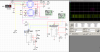
As you can see, the Q output is flatlining. I am following a schematic online which shows that all one needs to do is connect Q to D, but that doesn't seem to work. Any tips?

(Also please don't suggest I use JK flipflops instead, as I don't have the parts for it so wish to do it with D flipflops if possible, thanks!)
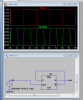
 

Attachments

  • dflip.png
    dflip.png
    32.2 KB · Views: 134

snake0

Mar 30, 2014
54
Joined
Mar 30, 2014
Messages
54
Sorry I uploaded the wrong picture, that was of a test circuit, I'm actually doing it with nand gates (i dont have a d-flip IC), I have gotten B to pulse but A shows as constantly 5V for some reason. Any ideas?
 

Attachments

  • dflip2.png
    dflip2.png
    57.4 KB · Views: 147

snake0

Mar 30, 2014
54
Joined
Mar 30, 2014
Messages
54
Ok my computer just froze and I hadn't saved the file, I just rebuilt it exactly the same but now there is a definite division... however its not 1/2 which is what it should be for a single d-flipflop
 

Attachments

  • dflip3.png
    dflip3.png
    34.2 KB · Views: 130
Last edited:

snake0

Mar 30, 2014
54
Joined
Mar 30, 2014
Messages
54
Actually i think i will try this with jk flips instead, brb buying parts!
 

snake0

Mar 30, 2014
54
Joined
Mar 30, 2014
Messages
54
Welp, same thing with the jks too..

Thoughts?
 

Attachments

  • jkflip.png
    jkflip.png
    56.7 KB · Views: 105

kpatz

Feb 24, 2014
334
Joined
Feb 24, 2014
Messages
334
Maybe it's something not set up right in your simulator? I created the D flip-flop version in LTSpice and it toggles properly. Try forcing unused inputs high.

Have you tried building the circuit with actual parts?
 

Attachments

  • flipflop.PNG
    flipflop.PNG
    25.5 KB · Views: 133

snake0

Mar 30, 2014
54
Joined
Mar 30, 2014
Messages
54
Hi kpatz,

Just tried building it IRL and it seems to work fine, however it's not entirely 1/2, it goes out of phase pretty quickly when driving LEDs, probably just a voltage issue though (I hope... gulp) I mean, there's no real room for error, Q just gives 1/2 the frequency
 

snake0

Mar 30, 2014
54
Joined
Mar 30, 2014
Messages
54
Forcing the other inputs HIGH worked in the simulator! (I think i tried forcing them LOW before as I forgot they are off when HIGH).

Thanks!
 

KrisBlueNZ

Sadly passed away in 2015
Nov 28, 2011
8,393
Joined
Nov 28, 2011
Messages
8,393
I may be missing something here, but I don't think that discrete gate circuit is a D flip-flop; I think it's a transparent latch. D flip-flops are edge-triggered, so the D input is just sampled at the instant when the clock goes high. While clock is high, changes on D won't have any effect on a normal D flip-flop. But with that circuit, the output will follow the D input all the time while the so-called clock input is high. It's not a clock input, it's an enable input for a transparent latch...
 

Arouse1973

Adam
Dec 18, 2013
5,178
Joined
Dec 18, 2013
Messages
5,178
I am no digital guy by far, it brings me out in a rash :) But I think Kris is right, the circuit shown has feedback from the output, is this right?

Adam
 

snake0

Mar 30, 2014
54
Joined
Mar 30, 2014
Messages
54
Just a word of caution for anyone building the JK, as I spent hours debugging a problem whereby it simply output at the same frequency instead of halving - you have to leave ~1Q and ~2Q floating! Pulling them HIGH breaks the frequency division, and pulling them LOW makes the JK output nothing at all. Doesn't happen like that in the simulator, not sure why this is the case, but in every of the 6 chips I tested this was true.
 

(*steve*)

¡sǝpodᴉʇuɐ ǝɥʇ ɹɐǝɥd
Moderator
Jan 21, 2010
25,510
Joined
Jan 21, 2010
Messages
25,510
Just a word of caution for anyone building the JK, as I spent hours debugging a problem whereby it simply output at the same frequency instead of halving - you have to leave ~1Q and ~2Q floating! Pulling them HIGH breaks the frequency division, and pulling them LOW makes the JK output nothing at all. Doesn't happen like that in the simulator, not sure why this is the case, but in every of the 6 chips I tested this was true.

Are you talking about the Q OUTPUTS? You would NEVER tie them high or low. Pulling them high or low is a waste, but as long as you're not overly enthusiastic you shouldn't do anything more than waste power.

edit (I think you are) The ~Q outputs are the Q-bar or Q' outputs, and are outputs, and should not be tied to a supply rail.
 
Last edited:

snake0

Mar 30, 2014
54
Joined
Mar 30, 2014
Messages
54
Indeed they were Q-bars. While we are on the subject, other than using an additional transistor, is there any configuration that allows Q-bar to sink current? For example if I gave +2.5V to Vcc and -2.5V to GND, in the Q=HIGH state would that make Q-bar = -2.5V?
 

(*steve*)

¡sǝpodᴉʇuɐ ǝɥʇ ɹɐǝɥd
Moderator
Jan 21, 2010
25,510
Joined
Jan 21, 2010
Messages
25,510
Q' can sink current when it is in the low state. It does not matter what the actual supply rails are.
 

snake0

Mar 30, 2014
54
Joined
Mar 30, 2014
Messages
54
That's good to know, thanks steve, maybe I can find a use for my common anode 7-segments now
 

snake0

Mar 30, 2014
54
Joined
Mar 30, 2014
Messages
54
Hi again! I successfully made a frequency counter in simulation, which works by ANDing a 555 pulse of a known period with the frequency then showing the binary value of amount of cycles via 4 JK flipflops (I use 6 in the real thing) which transpired during that period. The problem is that after building this in real life, it seldom works as I had hoped (I have had it produce accurate results about twice out of many tries).
When I switch on the circuit, many of the leds light up on their own, and any small disturbance in the board (say, if I knock it by accident) also causes the LEDs to randomly change state.
I wonder if there is anything fundamentally wrong with what I'm doing, as I have replaced connections on the board multiple times and it doesn't seem to help anything. Is there some kind of noise protection I should be employing?

By the way, in the real life version at present I have changed the values so that the output pulse and frequency period are in seconds not milliseconds, so I can see from another LED tied to the AND output exactly what value the final counter should show. The AND is producing the correct results, so it must be something further down the chain - in the flipflops.
 

Attachments

  • freqcount.png
    freqcount.png
    58.1 KB · Views: 135
Top