Maker Pro
Maker Pro

Creating Theater Magic

creamcorn

Jun 24, 2013
2
Joined
Jun 24, 2013
Messages
2
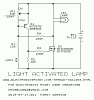
I need advice to create a simple circuit idea for a local theater to use. The idea uses two circuits created from two photo resistors, one LED, two batteries (voltage uncertain) and a few light bulbs. I have very little experience with small electronics, but I know if I can iron out the details someone else can make it.My idea is to make a street lamp on stage that is battery powered go on and off with the stage lights.To do this I would use a photo resistor on the top of the lamp post, that would be wired to a (9v?) battery and a LED. The LED would light up when the photo resistor detected the stage lights are out.
The LED would be stuck into the end of a small, short tube (maybe a short piece of a BIC pen). In the other end of the tube would be the second photo resistor. The photo resistor would be circuited to a larger battery and the three light bulbs for the street lamp
That second photo resistor would detect the LED- meaning when the stage is in a black out the street lamp would be out. When the stage lights come up, the street lamp also comes up. There would also be an on/off switch on the second circuit.
I am sure there is a need for capacitors, resistors and voltages. Any help is appreciated

Thank you
 
Last edited by a moderator:

BobK

Jan 5, 2010
7,682
Joined
Jan 5, 2010
Messages
7,682
I don't understand why two circuits are needed. Why can't you simply have a single photocell that turns on the street light when it sees light? (with it positioned so the street light itself does not illuminate it)

Bob
 

(*steve*)

¡sǝpodᴉʇuɐ ǝɥʇ ɹɐǝɥd
Moderator
Jan 21, 2010
25,510
Joined
Jan 21, 2010
Messages
25,510
I think creamcorn is thinking of having the LDR in series with the bulb.

This is an intuitive design based on what the various components do, however it doesn't work in practice.

What you need to do is to have the LDR control a transistor, and the transistor switches the bulb. It's like using a lever, the LDR can't pass a lot of current, but the small current it can pass can control a transistor. This small current is amplified by the transistor so that it is sufficient to turn a bulb on.

This page has a circuit that turns a light on in darkness. You want the reverse. Switch the position of the LDR and the 10k resistor (labelled R) to get the behaviour you want.

That circuit is very simple and may have various problems, including:

1) light turns on slowly as ambient light increases
2) light may not fully turn on.
3) limited power available to the lamp
4) transistor may get very hot in some circumstances
5) light may not go off if the LDR can "see" the bulb.

Some of these things can be fixed, others mediated.

If you have more information (especially the power of the bulb you want to turn on and off) then we can help develop a more practical circuit.
 

creamcorn

Jun 24, 2013
2
Joined
Jun 24, 2013
Messages
2
Thank you BobK and (*steve*) for taking the time to respond to my post.

(*steve*) - thanks for the advice. Good to know before spending too much time on it.

I will find out the power of the bulb tomorrow and would really appreciate your help developing a more practical circuit.
 

KrisBlueNZ

Sadly passed away in 2015
Nov 28, 2011
8,393
Joined
Nov 28, 2011
Messages
8,393
Hi creamcorn and welcome to the Electronics Point forums :)

Here is a circuit that will do what you want. It has hysteresis (Google it) so it switches ON and OFF cleanly. The switching threshold is adjustable.

attachment.php


It operates from a DC supply between 9V and 12V and can drive a lamp that draws up to 30 watts. You should build it on stripboard, also known as veroboard. Google stripboard construction and look in the tutorials section of this site for information about how to construct a circuit on stripboard.

Here are links to all the components on the Digikey web site. Most of these will be available locally apart from the MOSFET. You can get that from Digikey, or if you're in America and want to get the MOSFET from Radio Shack, let me know and I'll give you links to a suitable component that you can order from the Radio Shack web site.

VR1 (10k linear trimpot): http://www.digikey.com/product-detail/en/3306F-1-103/3306F-103-ND/84666
R1,2 (10k resistor): http://www.digikey.com/product-detail/en/MFR-25FBF-52-10K0/10.0KXBK-ND/13219
R3 (100 ohm resistor): http://www.digikey.com/product-detail/en/MFR-25FBF-52-100R/100XBK-ND/12795
R4 (100k resistor): http://www.digikey.com/product-detail/en/MFR-25FBF-52-100K/100KXBK-ND/13473
LDR1 (light-dependent resistor): http://www.digikey.com/product-detail/en/PDV-P8103/PDV-P8103-ND/480610
Q1 (2N3906 transistor): http://www.digikey.com/product-detail/en/2N3906TFR/2N3906D26ZCT-ND/458922
Q2 preferred device (NTD4906N N-channel MOSFET): http://www.digikey.com/product-detail/en/NTD4906N-35G/NTD4906N-35GOS-ND/2194521
Q2 alternative device (NTD3055 N-channel MOSFET): http://www.digikey.com/product-detail/en/NTD3055L104-1G/NTD3055L104-1GOS-ND/1484764

The battery and bulb must be rated between 9V and 12V and suited to each other. If the bulb draws, say, 30 watts, the battery must be able to supply about 3A for as long as the bulb needs to remain ON for.

As Steve mentioned, you need to make sure that the LDR cannot "see" the lamp, otherwise the circuit may not switch off when the other light is turned off.
 

Attachments

  • CREAMCRN.001.GIF
    CREAMCRN.001.GIF
    4.2 KB · Views: 173
Top