Maker Pro
Maker Pro

Corning PC-620 120V 1113W Repair

EastCoastToast

Dec 21, 2015
26
Joined
Dec 21, 2015
Messages
26
Hey guys, I've recently bought a hot plate for about $50 in hopes of repairing it for use. These generally are about $400-500 so it's worthwhile to attempt to fix it.

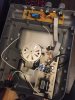
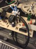
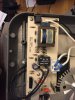
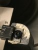
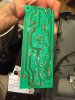
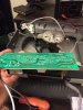
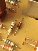
The circuit is composed of two PCBs. One which is connected to the power supply contains a triac, a transformer, a relay and the inputs/outputs for the motor and heater with various resistors and a component to determine rpm of the motor.

The second PCB contains a micro controller and the turnable joysticks that control the range of heating and motor speed.

I have a limited working knowledge of circuits. I've taken one course and messed around with 7 segments and disposable camera tasers. I'm not sure where to start with this repair and was wondering if anyone has any advice/suggestions.

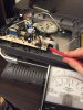
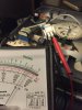
I have researched a few things, another posting talked about determining the resistance of the heater to determine whether it was broken or not. I tried and couldn't get a solid connection. Also the PCBs are made by ACT Corp of Rowlett,Texas.

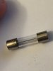
I was able to get the unit turned on and the motor turned the stirrer. I turned the heat on, heard a click and then turned off the heat and the stirrer no longer turns and the light doesn't come on when the heating element is on.

Thanks for taking the time to read this!
 

Attachments

  • image.jpeg
    image.jpeg
    276.4 KB · Views: 388
  • image.jpeg
    image.jpeg
    290.4 KB · Views: 323
  • image.jpeg
    image.jpeg
    257.4 KB · Views: 319

Tha fios agaibh

Aug 11, 2014
2,252
Joined
Aug 11, 2014
Messages
2,252
I would unplug that white plug next to that black relay and check the ohm reading of the element on the end of the plug. I'd guess it would be about 6 to 10 ohms? The 1113 watt rating is probably including the motor load.
 

73's de Edd

Aug 21, 2015
3,628
Joined
Aug 21, 2015
Messages
3,628
.


Sir EastCoastToast. . . . . . .

(Comments reflect being poked up earlier in the day, while later looking for a pic of the unit . . . .)

Gee . . . .I was not expecting a piece of lab equipment . . . . .I was expecting a hot plate to prepare your Cornish game hens upon.

I think that you "dun guuud" in your product / circuitry inspection and assigning device assessments.

"light doesn't come on when the heating element is on. " . . . . .


'is the heater heating ?

Any chance that the testing ended up blowing the main power fuse located completely across from the ROWLETT label beside the power transformer ?

The centrally located Triac seems to be related with the stirrer speed control with motor feed back info acquired from the
slotted disk optical interrupter. The other end of the motor shaft will be associated with the rotating of a "super magnet"

The centrally located conventional BLACK sugar cube relay of 120VAC @ 10 amp rating with a 9V coil seems to be the heater switching element, for that hefty of a heater element consumption.
The relay could be bad.

The heater wiring plugs in beside the relay, the first step I would be doing would be to unplug the heater wiring at the plug and ohm out the units resistance and then . . . AND THEN . . . . also ohm out each wire in reference to frame ground wire as seen as the GREEN/YELLOW trace wire at center bottom.

That confirms that the heater element has not broken down to ground.

A 1115 watt at 120 VAC would be ~ 13 ohms at that heated temperature, but our reading would deviate with a with COLD heating wire being ~ 10% higher . . . or possibly . . . its using a formed Calrod heating element, since that unit is using one massive and FINE cast housing.

Standing by


73's de Edd


.
 
Last edited:

73's de Edd

Aug 21, 2015
3,628
Joined
Aug 21, 2015
Messages
3,628
.


Hey you guys ! . . .a. .la . . .The Three Stooges


Addenda:

Residing right here on site Archives sits this 2005 comment on a like unit.
Most info comes from Messr Foley . . . . .but with my questioning his suspicioned
use of the Triac for heater control, instead of the conventional armature relay that sits right
beside the Heater connector plug.

https://www.electronicspoint.com/threads/corning-laboratory-hotplate-stirrer.56376/

73's de Edd


.
 

EastCoastToast

Dec 21, 2015
26
Joined
Dec 21, 2015
Messages
26
Hi Toast,
That comment of yours says there were other underlying faults already repaired?
Do you have a multimeter?

Martin

The posting said that the unit did not heat IIRC, I do have a multimeter the heater reads about 14.5 ohms which is within the range I believe.

I would unplug that white plug next to that black relay and check the ohm reading of the element on the end of the plug. I'd guess it would be about 6 to 10 ohms? The 1113 watt rating is probably including the motor load.

You were very close about 14.5 ohms!
 

EastCoastToast

Dec 21, 2015
26
Joined
Dec 21, 2015
Messages
26
.


Sir EastCoastToast. . . . . . .

(Comments reflect being poked up earlier in the day, while later looking for a pic of the unit . . . .)

Gee . . . .I was not expecting a piece of lab equipment . . . . .I was expecting a hot plate to prepare your Cornish game hens upon.

I think that you "dun guuud" in your product / circuitry inspection and assigning device assessments.

"light doesn't come on when the heating element is on. " . . . . .


'is the heater heating ?

Any chance that the testing ended up blowing the main power fuse located completely across from the ROWLETT label beside the power transformer ?

The centrally located Triac seems to be related with the stirrer speed control with motor feed back info acquired from the
slotted disk optical interrupter. The other end of the motor shaft will be associated with the rotating of a "super magnet"

The centrally located conventional BLACK sugar cube relay of 120VAC @ 10 amp rating with a 9V coil seems to be the heater switching element, for that hefty of a heater element consumption.
The relay could be bad.

The heater wiring plugs in beside the relay, the first step I would be doing would be to unplug the heater wiring at the plug and ohm out the units resistance and then . . . AND THEN . . . . also ohm out each wire in reference to frame ground wire as seen as the GREEN/YELLOW trace wire at center bottom.

That confirms that the heater element has not broken down to ground.

A 1115 watt at 120 VAC would be ~ 13 ohms at that heated temperature, but our reading would deviate with a with COLD heating wire being ~ 10% higher . . . or possibly . . . its using a formed Calrod heating element, since that unit is using one massive and FINE cast housing.

Standing by


73's de Edd


.

Working on this right now!
 

Tha fios agaibh

Aug 11, 2014
2,252
Joined
Aug 11, 2014
Messages
2,252
Take a picture of the back side of that circuit board with the relay on it.
73's de Edd is probably right that the relay has failed.
I'd try by bypassing the NO contacts and see if it heats. You could also check the element wire with a clamp on meter (if you have one) and see if its pulling any current.
 

EastCoastToast

Dec 21, 2015
26
Joined
Dec 21, 2015
Messages
26
Ok so when plugged clamped to ref green/yellow wire the white plug has no resistance reading. Referenced the resistors from the triac forward and they vary between significantly. On the left side of the PCB to the right of the sugar cube the 564 ohm resistor beneath the ribbon cable reads the same resistance as the heater when plugged in. A resistor with one black band to the left of the ribbon cable goes to ground...


Fuse looks good!
 

Attachments

  • image.jpeg
    image.jpeg
    260.4 KB · Views: 219
  • image.jpeg
    image.jpeg
    231.5 KB · Views: 212
  • image.jpg
    image.jpg
    97.1 KB · Views: 182
Last edited:

Tha fios agaibh

Aug 11, 2014
2,252
Joined
Aug 11, 2014
Messages
2,252
You can also check the voltage from one side of the element to the switched contacts on the relay. If the contacts are bad, you'll see a significant voltage difference.
That is, unless Moe or Larry have anything to add.
 

EastCoastToast

Dec 21, 2015
26
Joined
Dec 21, 2015
Messages
26
I can't get the PCB off because some dope stripped the M4 screw holding it down, how should I proceed?
 

Attachments

  • image.jpeg
    image.jpeg
    125.7 KB · Views: 193

Tha fios agaibh

Aug 11, 2014
2,252
Joined
Aug 11, 2014
Messages
2,252
If your very careful, hold the flat end of the triac with a small crescent wrench, and rotate the wrench and the board at the same time and see if it breaks free.
Don't force too much!
Option two; cut a small slot in the screw with a hack saw blade to turn it into a slotted screw.
Option three; drill the screw out with a drill bit about half the diameter as the screw head. Be careful not to drill past the screw head.
 

EastCoastToast

Dec 21, 2015
26
Joined
Dec 21, 2015
Messages
26
If your very careful, hold the flat end of the triac with a small crescent wrench, and rotate the wrench and the board at the same time and see if it breaks free.
Don't force too much!
Option two; cut a small slot in the screw with a hack saw blade to turn it into a slotted screw.
Option three; drill the screw out with a drill bit about half the diameter as the screw head. Be careful not to drill past the screw head.
I rotated with the crescent wrench and rotated the PCB, didn't feel comfortable going further.

I'll have to try the other two methods when I get back. I have a torx tap as well, what if I hammer that into the screw?
 

EastCoastToast

Dec 21, 2015
26
Joined
Dec 21, 2015
Messages
26
Got the board off! Had to use a dremel to cut the screw shaft unfortunately...

Looks like someone has freshly soldered the back of the board.

I'm going to try and get to the temperature sensor and see what's going on there. Also is this a thermal fuse in the last picture, the metallic red object
 

Attachments

  • image.jpeg
    image.jpeg
    255.3 KB · Views: 256
  • image.jpeg
    image.jpeg
    244.6 KB · Views: 212
  • image.jpg
    image.jpg
    123.4 KB · Views: 203

Tha fios agaibh

Aug 11, 2014
2,252
Joined
Aug 11, 2014
Messages
2,252
Not a good sign when someone else has worked before pawning it off on you.
Looks like they replaced the triac and transformer? (If I'm looking at the right connection)
That's not a fuse, I believe it to be a zener diode. (The clear looking component.)
 

EastCoastToast

Dec 21, 2015
26
Joined
Dec 21, 2015
Messages
26
They replaced the a few resistors and possibly the transformer I found a few things on the patents and here's an oriented image.
 

Attachments

  • IMG_5147.jpg
    IMG_5147.jpg
    333.7 KB · Views: 185
  • US07919731-20110405-D00001.png
    US07919731-20110405-D00001.png
    651.7 KB · Views: 230

EastCoastToast

Dec 21, 2015
26
Joined
Dec 21, 2015
Messages
26
Corning references that patent so they made some changes to the design, which includes your statement.
 

Tha fios agaibh

Aug 11, 2014
2,252
Joined
Aug 11, 2014
Messages
2,252
Look at the specs on the triac before proceeding, but I believe the outside two leads are triggered with a 5vdc supply from that white dip (comparator?)
Anyway, if you have 5v at the triac gate, it should send AC to the heat element.
Please be careful working around AC line voltage.
 
Top