Drew the circuit out myself, followed traces on the board, found part numbers for the thyristor and trigger and applied that to the drawing.
OK no probs ... the reason I asked was that you/whoever appeared to have mislabelled the 2 semiconductors
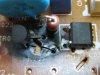
in relation to the LED. The M1L43 is a plain triac that 3 terminal TO92 case that looks like a BC546 transistor
to the left of the burn hole
Where as the TLP726 for as much as I could get info on is an opto coupled triac with which the LED is in internal part of and is that 5 pin black device labelled IC01J
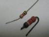
The resistor values as far as I could read them were (R03) 990R (white white brown gold)...it read 770R on the meter with part removed.
This is the one shown, the first band of white has flaked off after I removed it from the board.
The other (R02) 100R (brown black brown gold) and read 107R on the meter.
The first value seems like an odd value but the colours match...??
experience tells me and something you will learn too, resistors rarely show their correct colours when subjected to that much heat... the colours you see are likely to be pale cooked renditions of the originals
your resistance measurements are better to go off
990 Ohms ... not a standard value, but falls within the 10% tolerance of a 1k (1000 Ohm) resistor
770 Ohms is also not a standard value but it could be an 820 Ohm
They are probably both OK ( changing them wouldn't hurt)
As for the cooked board yeah!! haha
OK Options ....
clean the board thoroughly around the burnt area, removing as much of the burnt board as possible
this is essential as all that carbonised board will make a great conductor with 240V
you also have to consider why the burn up happened ... possibly a dry joint that started arcing at the termination solder pads of the missing resistor and that became a cascade effect with nearby solder pads as they heated up. Maybe that 3 pin triac and or the other one has also failed.
cheers
Dave