Maker Pro
Maker Pro

Colour organ jameco kit build virtual ground question

Sharkys

Nov 30, 2014
5
Joined
Nov 30, 2014
Messages
5
Hey I'm building a colour organ kit from jameco and planning to wire some rgb strips And run it with a dictation mic aimed at a speaker keeping it sort of mobile.

I've got all the pass thru op amps, the input amp done. Now I'm at a spot on the virtual ground where there's a v+ or Vcc arrow off the positive op amp input. Not sure how this input or source voltage differs from 12v or if it does. Any help appreciated

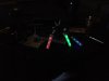
Will pos some board pics or schematics. The drawings are up at jameco colour organ kits page
 

Gryd3

Jun 25, 2014
4,098
Joined
Jun 25, 2014
Messages
4,098
Your virtual ground section will involve an opamp with the output tied to the inverting input (possibly with a feedback resistor) This output is also the 'virtual ground'.
The non-inverting input is connected to the middle of a voltage divider that is setup in a 1:1 ratio so that exactly half the source voltage is provided to the opamp. This input may or may not have a filter capacitor. Now it would be important to distinguish where the voltage source is actually coming from... if you have a 12V source but you are using a 5V regulator for your circuit, then the virtual ground circuit should be setup from that 5V regulator so the virtual ground is centered at 2.5V.
Seeing a diagram or schematic will help further, sorry but I'm not going digging for a schematic that you may or may not be using.
 

Sharkys

Nov 30, 2014
5
Joined
Nov 30, 2014
Messages
5
Hey it's a 12v input btw. You pretty much nailed it with the resistor setup. Feeling better about hooking it up now, thanks. I guess the Vcc is marked to show it's going to be aseparate amount.
 

Gryd3

Jun 25, 2014
4,098
Joined
Jun 25, 2014
Messages
4,098
Hey it's a 12v input btw. You pretty much nailed it with the resistor setup. Feeling better about hooking it up now, thanks. I guess the Vcc is marked to show it's going to be aseparate amount.
To be certain, take a look at the input on all other devices in your schematic.
Chances are they are all labelled Vcc, it's a common notation. If anything were to require a separate power source it would most likely be marked very clear.
What you need to be certain of for your circuit now though, is that the 'virtual ground' output of this portion of the circuit is actually used as the ground for the rest of the circuit where it calls for VGnd or similar. This may cause confusion as you now have 2 different grounds that you cannot confuse!

For your circuit, ground will be connected to the negative on the batter/AC-DC adaptor.
Virtual Ground is the output of this portion of the circuit, and will be treated as a ground for some of the components for the rest of your circuit. These will be specially marked.
You should only have one 'power' marked Vcc. If there is another notation or seperate supply used, it is most likely related to controlling a completely separate circuit... ie like 110V AC lightbulbs.

Once again, if you want some more clarity, copy/paste that schematic you are using and we can take a closer look.
I don't want to look myself in-case I grab the wrong one. I could end up giving you some poor advise. So far, I am attempting to give you some generic advice based on what I have seen so far.
 

Sharkys

Nov 30, 2014
5
Joined
Nov 30, 2014
Messages
5
hey, appreciated it. ill attach the schematic below

Have it all hooked up and blinking the LEDs once on connecting. nothing after that with the Vcc tied to the 12+ battery. My grounds and V grounds ( digital grounds on schematic) seem to be well routed .

Vcc is the only one marked that way .. and just one power source but as you commented the resistor setup will chop voltage in half so could be noted for that alone(maybe?) and my problem lies somewhere else.

schematic http://www.jameco.com/Jameco/workshop/diy/basicledcolororgan-fig11.jpg

project page http://www.jameco.com/Jameco/workshop/diy/ledcolororgan.html?CID=organ
 

Gryd3

Jun 25, 2014
4,098
Joined
Jun 25, 2014
Messages
4,098
Hrm, odd that it's labelled differently than the others.
Everything is 12+ and the VGround portion is Vcc.
I'd still treat Vcc as 12V though.

This circuit is essentially 3 parts.
You have your Virtual Ground. (Or Digital Ground) that is going to the non-inverting input of all other Opamps in the circuit.
You have your input buffer labelled U1.1 which sets the initial gain for the circuit.
You have your filters which are each setup to a different frequency. The input to each filter is fed from a potentiometer so that you can adjust how sensitive each stage is. To begin, I would set each of those potentiometers to the lowest value.

What kind of test equipment do you have?
If you have it setup and all it does is blink on initial power on, then there could be a wiring fault, or the input signal you are using is too weak.
 

Sharkys

Nov 30, 2014
5
Joined
Nov 30, 2014
Messages
5
hey thanks ill try that stuff tomorro and get back. ive tested lights, and the filters (by passing back to the input buffer). I've got a multimeter if playing with the inputs and dials doesnt work.
 

KrisBlueNZ

Sadly passed away in 2015
Nov 28, 2011
8,393
Joined
Nov 28, 2011
Messages
8,393
That's not a very good design.

The virtual ground, which they have labeled "GNDDIGITAL" for some reason, is created by U2 in the box in the bottom left corner, but U2 isn't needed. Just use R27, R28 and C15, and connect the centre point straight to "GNDDIGITAL" without U2. This will work fine because the virtual ground rail is only used to set up the bias on the four other op-amps and no significant current is drawn from it, so it doesn't need a buffer.

The audio input socket is connected upside down. The part that makes contact with the sleeve of the plug should be grounded, and the contacts should feed into U1.1. They can be connected together as shown.

The circuit should have several decoupling capacitors, for reliability. I suggest a 1000 µF 25V across the incoming power (with a diode in series from the power connector, for reverse polarity protection), and a 0.1 µF ceramic across the power pins of U1.

You will get a wider range of brightness in the LED indications if you insert resistors between the emitters of Q1, Q2 and Q3 and ground. Start with around 10Ω.

There are other problems but those are the most obvious I think.
 

Sharkys

Nov 30, 2014
5
Joined
Nov 30, 2014
Messages
5
Hey thanks I got it working with the Vcc as main power in and 12+ As more main power. Not sure if that's how it's meant to go or I'm skipping part of the virtual section thru to filters. Looks cool anyways for now
 

Attachments

  • image.jpg
    image.jpg
    82.9 KB · Views: 142
Top