rockrockmcrock
- Dec 19, 2011
- 41
- Joined
- Dec 19, 2011
- Messages
- 41
Hi guys,
This seems to be a very widespread issue in the classic car world, but no one has found an easy solution that I can see - I thought perhaps a guru here might be able to help - the classic car community would be in your debt!
The problem:
I want to retain some old bi-metallic gauges in one of my classic cars (got to keep it original on the dash right?). These older gauges are "bi-metallic electronic" (most Smiths, Jaeger gauges pre-79 were). However modern gauges (including 'classic' modern Smiths) work in a different way (i.e. potentiometer based). This means that modern 'sensors' for gauges are mostly 'reversed' in the way they work (more on this later) and that the original sensors for the old bi-metallic gauges are out of production, hard to find and very expensive. Of course without the right signal from the sensor the gauge will not work. Is there a simple circuit to make modern sensors work with old bi-metallic gauges?
How bi-metallic gauges and sensors work:
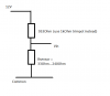
All gauges are 10v. The gauges work by a 'sensor' which acts as a variable resistor and limits the current on the gauge circuit in line with pressure. The current heats a coil wrapped around a bi-metallic strip in the gauge with responds by moving the needle on the gauge. Low pressure = high resistance (240 ohms) => no heating of coil & gauge needle reads low, high pressure = low resistance (33 ohms) => coil is at it's hottest & gauge needle reads high. The coil is inherently damped (thermo-damping) and the gauge has a linear(-ish) response to current.
How modern sensors work:
Most sensors are 10v. Modern sensors work the opposite way round but over roughly the same range. In other words, Low pressure = low resistance (33 ohms) => gauge needle reads low, high pressure = high resistance (240 ohms) => gauge needle reads high. If you put this modern sensor on the old bi-metallic gauge setup the reading's would be reversed (i.e. the needle would read high when at low pressure and low when at high pressure.
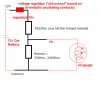
What the circuit would need to do:
Reverse the modern sensors output - i.e. when the sensor gives high resistance, allow more current to flow (i=v/r => 10/33 amps max?) on gauge circuit and visa versa. Not sure if this is a simple thing or a very complex ask!
Sorry for what might be a stupid question but I'm not an electronics wizard - I mess about with RT programming and classic cars so I just don't have that foundation knowledge of electronics needed to get me off the starting blocks on this one...
Thanks guys for any help - do a quick google and you'll see quite how many of us classic and vintage car guys have this issue, so you really would be doing us a favour!
RRMR
This seems to be a very widespread issue in the classic car world, but no one has found an easy solution that I can see - I thought perhaps a guru here might be able to help - the classic car community would be in your debt!
The problem:
I want to retain some old bi-metallic gauges in one of my classic cars (got to keep it original on the dash right?). These older gauges are "bi-metallic electronic" (most Smiths, Jaeger gauges pre-79 were). However modern gauges (including 'classic' modern Smiths) work in a different way (i.e. potentiometer based). This means that modern 'sensors' for gauges are mostly 'reversed' in the way they work (more on this later) and that the original sensors for the old bi-metallic gauges are out of production, hard to find and very expensive. Of course without the right signal from the sensor the gauge will not work. Is there a simple circuit to make modern sensors work with old bi-metallic gauges?
How bi-metallic gauges and sensors work:
All gauges are 10v. The gauges work by a 'sensor' which acts as a variable resistor and limits the current on the gauge circuit in line with pressure. The current heats a coil wrapped around a bi-metallic strip in the gauge with responds by moving the needle on the gauge. Low pressure = high resistance (240 ohms) => no heating of coil & gauge needle reads low, high pressure = low resistance (33 ohms) => coil is at it's hottest & gauge needle reads high. The coil is inherently damped (thermo-damping) and the gauge has a linear(-ish) response to current.
How modern sensors work:
Most sensors are 10v. Modern sensors work the opposite way round but over roughly the same range. In other words, Low pressure = low resistance (33 ohms) => gauge needle reads low, high pressure = high resistance (240 ohms) => gauge needle reads high. If you put this modern sensor on the old bi-metallic gauge setup the reading's would be reversed (i.e. the needle would read high when at low pressure and low when at high pressure.
What the circuit would need to do:
Reverse the modern sensors output - i.e. when the sensor gives high resistance, allow more current to flow (i=v/r => 10/33 amps max?) on gauge circuit and visa versa. Not sure if this is a simple thing or a very complex ask!
Sorry for what might be a stupid question but I'm not an electronics wizard - I mess about with RT programming and classic cars so I just don't have that foundation knowledge of electronics needed to get me off the starting blocks on this one...
Thanks guys for any help - do a quick google and you'll see quite how many of us classic and vintage car guys have this issue, so you really would be doing us a favour!
RRMR