Maker Pro
Maker Pro

Clarke CCRT266 Speed controller repair

camerart

Aug 18, 2010
135
Joined
Aug 18, 2010
Messages
135
Hi,
Can anyone help me to find the 8PIN chip for the Clarke CCRT266 Speed controller please?

Markings: SY (In a circle) 069B 201628C

Shown here:

Camerart
 

Attachments

  • Clarke CCRT266 Speed controller.jpg
    Clarke CCRT266 Speed controller.jpg
    199.1 KB · Views: 11

Harald Kapp

Moderator
Moderator
Nov 17, 2011
13,742
Joined
Nov 17, 2011
Messages
13,742
Your photo is too hazy to make out any detail. Please try again and upload a photo where we can read the inscription on the chip.
 

camerart

Aug 18, 2010
135
Joined
Aug 18, 2010
Messages
135
Your photo is too hazy to make out any detail. Please try again and upload a photo where we can read the inscription on the chip.
Hi H,
Ok, I'll retry.

The markings on the chip: SY (In a circle) 069B 201628C

C.
 

camerart

Aug 18, 2010
135
Joined
Aug 18, 2010
Messages
135
Hi,
Here is a clearer image of the PCB.
C.
 

Attachments

  • Clarke CCRT266 Speed controller.jpg
    Clarke CCRT266 Speed controller.jpg
    245.8 KB · Views: 10

Harald Kapp

Moderator
Moderator
Nov 17, 2011
13,742
Joined
Nov 17, 2011
Messages
13,742
The chip is a SY069B. The other number is probably the date code year 2016, week 28 and not relevant for identification.
Do you know Chinese? Unfortunately this is the only page I found where this chip is for sale.
This page is in English but doesn't help much more.

Why do you think the chip is at fault? I'd put my bet on the MOSFET (NCE6050). This MOSFET, driving the motor load, is subject to much more stress and therefore more likely to fail.
 

camerart

Aug 18, 2010
135
Joined
Aug 18, 2010
Messages
135
The chip is a SY069B. The other number is probably the date code year 2016, week 28 and not relevant for identification.
Do you know Chinese? Unfortunately this is the only page I found where this chip is for sale.
This page is in English but doesn't help much more.

Why do you think the chip is at fault? I'd put my bet on the MOSFET (NCE6050). This MOSFET, driving the motor load, is subject to much more stress and therefore more likely to fail.
Hi H,
Thanks for your research.

I'll try to find the PDF, so I can see the PIN outs.

I actually don't think this chip is at fault, and agree that the MOFET is at fault. I have removed it and my amateur readings from it appear to prove it's faulty. When I opened up the drill, the MOFET was skewed as if it had got too hot and moved. I have MOSFETs that I can try, but first I wanted to draw the Schematic, in case it goes wrong again.

C.
 

73's de Edd

Aug 21, 2015
3,628
Joined
Aug 21, 2015
Messages
3,628
Sir camerart . . . . .

If you came into this session knowing " nuttin ".. . . . . . rejoice . . . .as when you leave, you should leave knowing a little more than . . . " nuttin ".

So o o o o o o . . . . . you seem to have yourself a DREMEL rotary motor tool wannabe there . . .hunh h h h ?

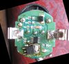
First, do you have any more relevant info on the unit, as to whether it stopped or will not run or runs full speed, smoked, or was cutting in and out intermittently before failing ?

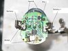
I see your second photo now, and that confirms that you are cognizant as to what some of the components are. I had already started on a blowup mark-up of what you had posted initially . . .it seems to work better for marking up..

I was also perceiving of the YELLOW circles as being the units speed control pot. The BLUE circles, as being a very low value resistor between those connections , to get some max current limiting , as well as cross power B+ connection to the other side of the board
All of the deteris on the board along with not exactly being in macro focus, inhibited my seeing if there was a dimple on the IC where I have inserted the YELLOW semicircle index. ( Confirm)
That then would verify my PROPER assignment / placement of the Pin 1 of the IC.

Now tell me that you do / did an AWFUL lot of plastic or epoxy grinding with this unit . . . . . by all of the surfactal chaff presence.

I sort of expect that IC to be either a comparator or op amp that is being pressed into application as a variable pulse width generator / driver to feed the gate of the power FET.

In my " Reading " of the PCB foil, we see that the FET's Drain-Source is completeing the negative power leg of the DC motor path to ground.

I also am skeptical of the fault being with the IC

Firstly . . . . is your battery pack presently charged up to FULL current / power capability or OOOOOOOOMMMMMMMPPPPHHHH !
If that is being of no question, then the problem of a commutator segment(s) or brush erosion within the DC motor would be a consideration.
Particularly if the unit has received LOTS of use.

Second main consideration would be the failure of the POWER FET / power electronic switch. Should it be shorted from D-S the unit would be running continously at full speed.
If bad in its second manner . . . . . it would not be responding to the variable drive being applied to its GATE, to enact D-S conductivity to run the motor..

what to do . . .what to do . . .WHAT TO DO . . . .?

Initially, see if you can enact a connection of the battery power pack to the controller boards two side contact tabs via the use of two test leads witn their paired clip on connectors, between the B+ and B- side spring connectors.
If by advancing the speed pot and the unit is then found inoperative, taking the end tip of the blade of a mini pocket sized STANDARD screwdriver blade and shorting across the D-S of the power FET should have the unit running at full speed for that instance of contact. That means motor health and its series arranged brush-field***-rotor continuity for operation is complete. (*** unless its using a permanent magnet surround, instead of a field winding.)
Then try a 100 ohm resistor, temporarily touched from Drain to Gate to see if the motor responds.
If that works . . .only then, do we start questioning the IC.

On the IC . . . . Harald has done better than I . . . if he found any mention of that SY069 amongst the Ali Express IC supply circles.

What I am seeing . . .

In reading that unit with my assigned indexing of pin 1.
I see R9-R6-R7-speed pot and the sole C1 timing capacitor relating to the variable pulse width drive generator circuitry.
That circuitry is all being within the RED indexed boundaries.
I see pin 2 going over to be the chips ground connection and pin 8 working its way up a foil path to a 300 ohm R4 to get Vcc power for the chip.
Probably, there is the forementioned low value power resistor between the BLUE dots.
I HIGHLY suspicion that the nearby R5 resistor, is coupling the variable chip drive into the Gate of the power FET.

ASIDE . . . .rather than overheating of the FET, SURELY, the adljunct discoloration I am seing is just from sloppy rosin residue , being left uncleaned from the board, at factory install time..

Over to the right, I inserted what would be the use of a typical 555 for a motor control circuit of a power FET, but one can see that the pin outs don't agree for that common IC . . . . but you can see, how the other major components are relating to your units design.

Waiting for your feedback from your observations and tests.


Photo Referencing . . . . .


KIaHJcI.jpg

https://i.imgur.com/KIaHJcI.jpg

73's de Edd . . . . .


With my old man I never got no respect. As a kid, I once asked him,
"How can I get my kite in the air?"
He told me to run off a cliff.

 
Last edited:

73's de Edd

Aug 21, 2015
3,628
Joined
Aug 21, 2015
Messages
3,628
'lebenteenth hour addenda . . . .

In tracking down Sir Haralds link, one cell gave your circuit as a small snippet, which I now place here . . .
I was surprised at the low value of timing capacitor, so its innards must basically be FET technology related..

upload_2019-3-4_17-10-3.png
 

camerart

Aug 18, 2010
135
Joined
Aug 18, 2010
Messages
135
'lebenteenth hour addenda . . . .

In tracking down Sir Haralds link, one cell gave your circuit as a small snippet, which I now place here . . .
I was surprised at the low value of timing capacitor, so its innards must basically be FET technology related..

View attachment 44809
Hi,
I just did the same! The schematic, is as the drill circuit, so that gives a bit of clarity.

The drill is not mine, and I think it has been used for grinding solder and copper, both of which are sticky, so would put a load on it. It is used to sculpture, and I'm repairing it in payment for one of them.

As you can see, by the first image, the MOSFET is skewed, and I imagine it got so hot, that it moved, then the dill went full speed, then packed in.

I'll fit a new MOSFET, and see if it comes to life again.
C
 
Last edited:

Harald Kapp

Moderator
Moderator
Nov 17, 2011
13,742
Joined
Nov 17, 2011
Messages
13,742
the MOSFET is skewed,
It is not only skewed, it is off the pads, You may even have a chance to revive the controller by simply soldering the MOSFET correctly back in place.
 

camerart

Aug 18, 2010
135
Joined
Aug 18, 2010
Messages
135
Hi H,
I will try that first.

Is there a resistive test, for MOSFETS?
C.
 

Harald Kapp

Moderator
Moderator
Nov 17, 2011
13,742
Joined
Nov 17, 2011
Messages
13,742
Is there a resistive test, for MOSFETS?
Unfortunately not really. You'll have to apply sufficient gate-source voltage to make the source-drain channel conductive.
You can test the source-drain channel without gate-source voltage using the diode test setting of a multimeter. A N-channel MOSFET as the NCE6050K should show no conduction with the positive test lead to drain and the negative lead to source. Swapped test leads should reveal the so called body diode between source and drain. If the MOSFET shows no short circuit between source and drain it will not hurt putting it back in place and check if the controller is working then.
 

camerart

Aug 18, 2010
135
Joined
Aug 18, 2010
Messages
135
Unfortunately not really. You'll have to apply sufficient gate-source voltage to make the source-drain channel conductive.
You can test the source-drain channel without gate-source voltage using the diode test setting of a multimeter. A N-channel MOSFET as the NCE6050K should show no conduction with the positive test lead to drain and the negative lead to source. Swapped test leads should reveal the so called body diode between source and drain. If the MOSFET shows no short circuit between source and drain it will not hurt putting it back in place and check if the controller is working then.
Hi H,
I tried testing with my meter, but it wasn't clear.
Am I correct, that if the MOSFET does have a short from source and drain, then won't the drill run flat out, and I can switch it off with no farther damage?
C
 

Harald Kapp

Moderator
Moderator
Nov 17, 2011
13,742
Joined
Nov 17, 2011
Messages
13,742
Am I correct, that if the MOSFET does have a short from source and drain, then won't the drill run flat out, and I can switch it off with no farther damage?
Yes, that should be o.k. that way.
 

camerart

Aug 18, 2010
135
Joined
Aug 18, 2010
Messages
135
Yes, that should be o.k. that way.
Hi H,
With the MOSFET in, it only runs at full speed.

I took the MOSFET off, and connected an oscilloscope to the GATE, and sure enough, when moving the speed control, the square wave went from almost always off to almost always on.

I'll order some MOSFETS, and let you know what happens.
C.
 

73's de Edd

Aug 21, 2015
3,628
Joined
Aug 21, 2015
Messages
3,628
Sir camerart . . . . .

The reading of a bad power FET should be as apparent as if you had tested for a short, by touching your two meter probes to each other.
And yes, that then installed bad FET should instantly . . . .as soo as power was connected . . . .have the motor runnng at full speed , until the pawer was disconnected.
Also . . . this advice . . . .
1 . . . . .The use of at least a 50 watt iron . .. or an adjustable heat level soldering station . . so that it can be cranked up to max. So that you won't be frying the board to foil lamination while the heat of a lesser powered iron is trying to come up to solder melting temperature.
2 . . . . . The removal of all of the old solder coating from the solder pads, in case its crappy all tin. Then the recoating of the pads with fresh . . . flux bearing . . . 60/40 solder and excess removal down to a just coating level. This being done on both the soldering pads and the terminals of the power FET.
3 . . . . .The specified 50 watt soldering iron heat capacity is right at minimalistic for heat level capacity WITHIN a reasonable speed of heating ability . . . of the mass to ( heat sink tab of the power FET ) be rapidly brought up to solder melting temp.
Then, the warming up of its pads and then reflowing both tab and pad up to reflow soldering temp when into place.
Then the gate and source tabs are reflow soldered..
4 . . . . Finally, the soldering iron tip needs to be tinned to the point of appearing totally chrome plated. That way when the few drops of fresh solder are applied to the pad of the FET Drain tab, the already molten drops of solder GREATLY enhance the bringing of the cluster up to reflow temperature.
Then take iron away and cool down of the joint.

Ask, if you would like my further suggestions , as the same type of use, should result in the same conditions again.

73's de Edd . . . . .

I went to a bookstore and asked the saleswoman, "Where's the self help section ? "
She said that if she told me, it would defeat the purpose.
 

camerart

Aug 18, 2010
135
Joined
Aug 18, 2010
Messages
135
Hi,
Sorry for the delay, I didn't receive a notice of your post.

Anyway, I centred the Mosfet, and it ran ok, and has been used for over 6months ok.

A couple of weeks ago, the owner gave it back to me, broken again. I changed the Mosfet, no fix, so I checked the motor. The motor has lost a few windings on the armature I think, so runs in bursts.

We ordered a new motor, but even though looks the same doesn't have a slot for the anti-rotation probe to fit. I'll get permission to cut of the probe and glue it in.

Cheers, C
 
Top