Maker Pro
Maker Pro

Chemetron wirefeeder - trying to salvage dc motor speed control

brbeardm

Oct 8, 2012
11
Joined
Oct 8, 2012
Messages
11
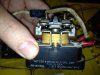
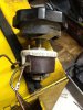
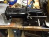
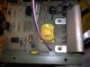
I have a Chemetron wirefeeder that I am using the motor and I want to use the speed control out of the control box to control the nice motor it had in it...but I am having trouble figuring the wiring schematic out. I've attached the schematic and the two parts that I think I need to wire. I could use some help making sure I've salvaged all the parts I need to run the motor. I have the potentiometer as well that is mentioned on the schematic. Any help would be appreciated.

I have a chemetron wirefeeder that I am trying to isolate the dc motor speed control circuit from all the other welding circuits. I want to use the motor for my metal lathe to control low speed fine cuts on the carriage feed. I would appreciate any help on this project!

here's the link to pics of the schematic
https://www.electronicspoint.com/ch...g-salvage-dc-motor-speed-control-t253137.html
 

Attachments

  • Picture1 (640x401).jpg
    Picture1 (640x401).jpg
    40 KB · Views: 435
  • schematic (800x500).jpg
    schematic (800x500).jpg
    81.3 KB · Views: 2,444
Last edited by a moderator:

CDRIVE

Hauling 10' pipe on a Trek Shift3
May 8, 2012
4,960
Joined
May 8, 2012
Messages
4,960
I had to choose which one of your two threads to respond to. I chose this one because it contains what you want to re-purpose the motor for. It looks like the components for the motor control are as follows:

Speed Control Block
CR2 Relay (CR2 shown as circle is the coil)
S1 (DPST) Switch. CR2 Coil uses one set of contacts.
P1 Speed Control Pot (5K @ 25W)
Barrier Block
R 5Ω @ 10W 'Breaking Resistor' Variable
4A Fuse
Molex Connector (Pins: 1 &12 for CR2 Coil. Pins: 13 & 14 for P1 Speed Control Pot)

As far as connectors go, you'll have to decide what you want to keep. Not sure how you're going to use this as a carriage feed motor though. It has no reverse circuitry. We also have no info on this motor like Hp, RPM, Current Draw, Duty Cycle. Since the fuse is only 4A and it protects the entire circuit, I have assume this is a very small motor. What size / model lathe do you have. Wild guess... Harbor Freight Mini? ;)

Chris
 
Last edited:

brbeardm

Oct 8, 2012
11
Joined
Oct 8, 2012
Messages
11
thanks for you help Chris. I have some feedback and then a few questions comments:

I got this idea from TubalCain on youtube... he has machinists videos there, great videos ... he made a mod to his carriage feed to slow it down for fine cuts ...
Power Carriage Feed Mod

My Lathe is a 1944 Logan 10" lathe, freshly restored with VFD 3-Phase speed controlled motor

I have a few questions from your response.
1. S1 --- how can I eliminate this switch? (would I jumper 2CR-#2 to SpeedControl-#6 terminals)?

2. Barrier Block --- do I need this if I eliminate S1 (I'm not using anything on the other set of contacts on S1)

3. on my 115V AC feed to the 4AMP circuit does BLACK load wire go into the fuse... or WHITE neutral...

thanks,
Brian
 

CDRIVE

Hauling 10' pipe on a Trek Shift3
May 8, 2012
4,960
Joined
May 8, 2012
Messages
4,960
thanks for you help Chris. I have some feedback and then a few questions comments:

I got this idea from TubalCain on youtube... he has machinists videos there, great videos ... he made a mod to his carriage feed to slow it down for fine cuts ...
Power Carriage Feed Mod

My Lathe is a 1944 Logan 10" lathe, freshly restored with VFD 3-Phase speed controlled motor

I have a few questions from your response.
1. S1 --- how can I eliminate this switch? (would I jumper 2CR-#2 to SpeedControl-#6 terminals)?
Why do you want to? It's the power switch to the motor relay CR2.
2. Barrier Block --- do I need this if I eliminate S1 (I'm not using anything on the other set of contacts on S1)
I see no reason to eliminate it. It provides connections to the motor.
3. on my 115V AC feed to the 4AMP circuit does BLACK load wire go into the fuse... or WHITE neutral...
The fuse should always be in the hot (black) leg.
thanks,
Brian

You're also going to need a DPDT switch for use as a FWD/REV switch. We might be able to replace S1 and CR2 with a DPDTCO switch but we need the motor info. Post the motor specs.

Brian, your invited to join us.
http://finance.groups.yahoo.com/group/loganlathe/?yguid=197128120

Yes, I'm quite familiar with TublaCain. Is your motor the same motor he used in his video? I have a Logan 920 and a SB Heavy 10 and my wife has a Jet Midi wood lathe.

Chris
 

brbeardm

Oct 8, 2012
11
Joined
Oct 8, 2012
Messages
11
I need to identify the parts correctly

Ok, sorry Chris. I am not following on the component names. I see "CR2 Relay" and "CR2 Coil" in your response. Is this the same thing? I'm attaching some pics to identify some of this stuff to make sure I know what you are talking about. on the diagram, I see 2CR(with circle around it) and 2CR(no circle) are these different component references?

Is the CR2 Coil Power Relay you reference have 11 pins in a circle configuration and plugs into the Ampenol block (pic) attached?

S1 is an "inch switch" (pic) which means it pulses the motor to burst 1 inch of wire... it's not an on/off switch... actually the unit doesnt have one... i assume the wirefeed gun controlled the on/off when pressed... S2 is for flux/solid wire selection. I can wire in a On/Off and Rev/Fwd later once I get the motor running on the potentiometer... I'm ok bypassing this for now. Can you help me bypass it to make the motor just run with speed control when plugged in?

I am sorry for my lack of knowledge here. i think if I can nail down CR2, I'll be a lot closer...

I am working on figuring out the motor... it is the same as the one on tubalcain's video, just a slightly newer gear box... It's a 2-wire DC motor, I'm guessing.. 24v motor... square flange mount - leeson perhaps... there is absolutely no numbering or information on it... i hook a 12v 10A batter charger to it and it turns low Rpm with tons of torque... i can't stop the thing with pliers...very strong. at 2A it runs slightly slower Rpm but still strong torque.
 

Attachments

  • coil-2CR-circled.jpg
    coil-2CR-circled.jpg
    149.1 KB · Views: 256
  • switches2.jpg
    switches2.jpg
    146.5 KB · Views: 1,156
Last edited:

brbeardm

Oct 8, 2012
11
Joined
Oct 8, 2012
Messages
11
Other components

Chris, some other components that I wanted to show you pics of that are not currently wired in.
 

Attachments

  • 28VDC coil.jpg
    28VDC coil.jpg
    141.9 KB · Views: 238
  • relaycoil.jpg
    relaycoil.jpg
    138.3 KB · Views: 266

CDRIVE

Hauling 10' pipe on a Trek Shift3
May 8, 2012
4,960
Joined
May 8, 2012
Messages
4,960
The Barrier Block is a black Bakelite terminal block marked 1 thru 8 in the left photo.

https://www.electronicspoint.com/attachments/5765d1350089168-chemetron-
wirefeeder-trying-salvage-dc-motor-speed-control-picture1-640x401-.jpg

The part connected to the switch on the right is a Selenium Rectifier, which is unmarked but in series with 1TD coil on your schematic. The component on the left connected to S1 is a Varactor Diode marked 6R52'SA5D5 on the schematic.

5796d1350280492-chemetron-wirefeeder-trying-salvage-dc-motor-speed-control-switches2.jpg


Brian, unless we take a different tac this thread will drag on forever. Let me draw a schematic, including reverse circuitry. This way you'll know what parts to keep and what to discard. Tell us how many pins S2 has and it's ratings. From the photo, it looks like a DPDT but it's not a clear photo.

By the way, your photos tell me this was made when things were built to last, just like that Logan!. ;)

Chris

Edit: I just noticed that S2 is drawn as a DPDT switch. Post the specs.
 
Last edited:

CDRIVE

Hauling 10' pipe on a Trek Shift3
May 8, 2012
4,960
Joined
May 8, 2012
Messages
4,960
Please post a photo of the P1 'Speed Control Pot'. If it's really 25W it's going to be a large wire-wound pot. For the record; if it is 25W then the speed control circuit is very primitive and very inefficient. That's a lot of wasted power!

Chris
 

brbeardm

Oct 8, 2012
11
Joined
Oct 8, 2012
Messages
11
more pics

Chris, here's the pics. one goof. I labled the switches wrong in the pic. I'm reposting that pic to properly label the switches and component names you gave me. the DPDT is really S2 which was the Flux or Solid wire "selector switch" It's as it should be on my new pic.

I threw in a pic of my sweet Logan 200, first cuts after complete restore! Ready for another 60 years!

I appreciate your help. A new schematic would be perfect. thanks, Brian
 

Attachments

  • switches2.jpg
    switches2.jpg
    148.8 KB · Views: 206
  • S2-selectorswitch.jpg
    S2-selectorswitch.jpg
    128.7 KB · Views: 237
  • S1-inchswitch.jpg
    S1-inchswitch.jpg
    134.5 KB · Views: 205
  • 5KohmPot.jpg
    5KohmPot.jpg
    141.7 KB · Views: 199
  • gearmotor.jpg
    gearmotor.jpg
    145.1 KB · Views: 210
  • IMG_1497.jpg
    IMG_1497.jpg
    143.7 KB · Views: 256

CDRIVE

Hauling 10' pipe on a Trek Shift3
May 8, 2012
4,960
Joined
May 8, 2012
Messages
4,960
Well P1 is as big as I imagined it to be. It's too bad you don't have the schematic of the speed control module, we'd love to see it.

Here's how I would wire it using original components only,

Chris
 

Attachments

  • LatheCarFeed.JPG
    LatheCarFeed.JPG
    57.9 KB · Views: 360

brbeardm

Oct 8, 2012
11
Joined
Oct 8, 2012
Messages
11
Chris thanks, I need help to positively identify the 2CR(coil) and the 2CR(A&B)-motor start/stop relay components... did I post pics of these that you can call out to me. I think I follow everything else on the diagram. Thanks for the help! Brian
 

CDRIVE

Hauling 10' pipe on a Trek Shift3
May 8, 2012
4,960
Joined
May 8, 2012
Messages
4,960
Chris thanks, I need help to positively identify the 2CR(coil) and the 2CR(A&B)-motor start/stop relay components... did I post pics of these that you can call out to me. I think I follow everything else on the diagram. Thanks for the help! Brian

The 2CR relay will have a 115VAC coil and should be marked as such. By the way the old girl looks great! Nice restoration!! Is that a 1-1/2" spindle?

Chris
 

brbeardm

Oct 8, 2012
11
Joined
Oct 8, 2012
Messages
11
ahh got it so 2CR relay is the same relay... i'm only using 1 of the 3 relays i have to make this work, is that correct? Here's a PIC of 2CR.

yes my gal is a 1-1/2" spindle with a sweet 6 jaw buck chuck!
 

Attachments

  • 2CR(coil-relay).jpg
    2CR(coil-relay).jpg
    149.1 KB · Views: 225

brbeardm

Oct 8, 2012
11
Joined
Oct 8, 2012
Messages
11
relays I don't need...

I don't need these based on your revised schematic
 

Attachments

  • 28VDC coil.jpg
    28VDC coil.jpg
    141.9 KB · Views: 174
  • relaycoil.jpg
    relaycoil.jpg
    138.3 KB · Views: 193

CDRIVE

Hauling 10' pipe on a Trek Shift3
May 8, 2012
4,960
Joined
May 8, 2012
Messages
4,960
ahh got it so 2CR relay is the same relay... i'm only using 1 of the 3 relays i have to make this work, is that correct? Here's a PIC of 2CR.

yes my gal is a 1-1/2" spindle with a sweet 6 jaw buck chuck!

Yes, relay 2CR should have 8 terminals, 2 terminals are the 115VAC coil, while the remaining 6 are double pole double throw contacts. S1 is a double pole single throw switch. It has 4 terminals. S2 is a double pole double throw switch with 6 terminals.

When I drew the schematic I retained the Chemtron component names but added "A" & "B" contact designations to indicate it's the same switch or relay.

I don't need these based on your revised schematic

No, but I would not throw out classic US made parts like those. In fact anything not used should be boxed and put on a shelf.
 

CDRIVE

Hauling 10' pipe on a Trek Shift3
May 8, 2012
4,960
Joined
May 8, 2012
Messages
4,960

Attachments

  • LatheCarFeed.JPG
    LatheCarFeed.JPG
    64.5 KB · Views: 292
Last edited:

brbeardm

Oct 8, 2012
11
Joined
Oct 8, 2012
Messages
11
Chris - You are the ObiWan Jedi-Knight of electronics. I finally got time last night to wire up the new schematic you provided above and the motor runs perfectly... the POT brings it down real slow to a few RPMs...with loads of torque... should power my carriage on the logan real nice, for super fine final cuts, just like tubal cain!

Now on to hooking this up to the lathe. I will post some PICs and youtube vids when I get this setup

Thanks so much for all your help
 
Last edited:

CDRIVE

Hauling 10' pipe on a Trek Shift3
May 8, 2012
4,960
Joined
May 8, 2012
Messages
4,960
Glad to hear that. It's always nice when a plan comes together. Many of us can spend copious amounts of time on a topic and never know if the OP ever used the information given or constructed the circuit drawn. So, it's always rewarding to hear back from the OP.

I do have a question though. Is there a schematic of the Speed Control circuit? If so, I'd appreciate seeing it.

I'll look forward to seeing your pix and vid.

Have fun making chips!

Chris
 
Last edited:

brbeardm

Oct 8, 2012
11
Joined
Oct 8, 2012
Messages
11
the goods !!!

thanks Chris, here's some shots of the motor control barrier block... looks very nicely laid out. And here's a video shot on Youtube of the motor running... now please excuse the wire chaos... i will spend some time getting this all routed and synched up with zip ties this weekend and will probably be transplanting the components to a gray wall utility box... rather than the chemetron yellow box... it will need to blend in with my nice Logan restoration!


Attachments

  • mcb1 (800x600).jpg
    mcb1 (800x600).jpg
    53.9 KB · Views: 191
  • mcb2 (800x600).jpg
    mcb2 (800x600).jpg
    29.9 KB · Views: 203
  • mcb3 (800x600).jpg
    mcb3 (800x600).jpg
    53.6 KB · Views: 191
  • mcb4.jpg
    mcb4.jpg
    144.3 KB · Views: 213
  • mcb5 (800x600).jpg
    mcb5 (800x600).jpg
    56.4 KB · Views: 207
  • mcb6 (800x600).jpg
    mcb6 (800x600).jpg
    52.1 KB · Views: 192
  • mcb7 (800x600).jpg
    mcb7 (800x600).jpg
    57.2 KB · Views: 182
Top