About the transistors- I couldn't get the once specified in that page (you don't have to go there again) so I used other low noise transistors.
Maybe I should just replace them? The power supply is intended to be used only for the pre-amp.
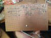
I will go over the wiring a few more times to verify that it's correct (or not).
I guess this project was too much for me, maybe I should have bought a ready phono stage for the price of the parts :/
What do you think I should do to make the most of this project? i don't want all tge efforts and money I've put in it to go in vain.
Also I appreciate your help a lot!! Honestly I feel uncomfortable with all the time you've put into finding my stupid mistakes.
Maybe I should just replace them? The power supply is intended to be used only for the pre-amp.
I will go over the wiring a few more times to verify that it's correct (or not).
I guess this project was too much for me, maybe I should have bought a ready phono stage for the price of the parts :/
What do you think I should do to make the most of this project? i don't want all tge efforts and money I've put in it to go in vain.
Also I appreciate your help a lot!! Honestly I feel uncomfortable with all the time you've put into finding my stupid mistakes.
 )
)