Maker Pro
Maker Pro

Capacitor discharges rapidly

Emam

Jul 7, 2014
63
Joined
Jul 7, 2014
Messages
63
Dear all,
I have a very strange problem.
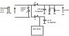
I have the following circuit (picture attached):
upload_2014-8-26_12-14-58.png

The circuit receives discrete pulses with 7.5 V amplitude and 2.5 A of current over 1-2 ms. The voltage is then stabilzed by a zener voltage at around 5.6 V. Then the capacitor of 150 uF will store the energy and keep the voltage at a quasi-stable state during long time (over seconds...). This capacitor is a SMD tantalum capacitor.
There is also an Asic circuit (with quartz, reset circuit etc.) but they are not of interest in my problem!

My problem:
For some reasons, we should put this circuit in a device generating a high mechancial force (without damaging the circuit). So the circuit is under very high force (something like high air pressure) for a few seconds.
After this test,we recover the circuit. We understood that after the test, our 150 uF capacitor fails to store the energy. So it discharges very rapidly. We checked the capacitor and it is not broken.

My questions:
Could you please tell me that in this case:
1. Is there any problem with the circuit itself (without considering the mechanical test)?
2. Is it the mechanical test which can cause the circuit to fail?
4. What can happen inside this kind of capacitor to fail?

Thank you very much for your help and bests regards.
l. Ram
 

Attachments

  • upload_2014-8-26_12-13-4.png
    upload_2014-8-26_12-13-4.png
    100.1 KB · Views: 105
Last edited:

Arouse1973

Adam
Dec 18, 2013
5,178
Joined
Dec 18, 2013
Messages
5,178
Why do you think it's the capacitor. There are other components that will cause a faster discharge that makes it appear as if the capacitor has lost capacitance. I think high pressure effects carbon resistors and it may well reduce the value, but I would have to look into this. Are you using carbon resistor by any chance?
Adam
 

Emam

Jul 7, 2014
63
Joined
Jul 7, 2014
Messages
63
Thank you for your reply.
I use SMD type thick film resistors.
(REF: RH73H2A15MKTN)
Do you beleive that this could be the problem?
Otherwise, could diodes also be the problem?

Thanks and Bests regrds
 

Harald Kapp

Moderator
Moderator
Nov 17, 2011
13,740
Joined
Nov 17, 2011
Messages
13,740
Any component could be he problem if it is not rated for the amount of pressure it experiences in your design.
You should start analyzing the components one by one after such a test to locate the faulty one. For example: remove the capacitor from the circuit, charge it and observe the discharge curve with a high-resistance voltmeter. Also apply power to the circuit which is normally powered by the capacitor and measure the current consumption.

As modern electronic components are delicate devices and are very small, it is well possible that high pressure creates short circuits (even minuscule ones).
 

KrisBlueNZ

Sadly passed away in 2015
Nov 28, 2011
8,393
Joined
Nov 28, 2011
Messages
8,393
Also, what part numbers are the diodes? Is D1 a zener diode? And are D2 and D3 just normal diodes? The symbol you have used is not a diode or zener diode symbol.
 

shrtrnd

Jan 15, 2010
3,876
Joined
Jan 15, 2010
Messages
3,876
I don't know, but I'll mention what I'm thinking. The surface mount caps have metal end-caps for connecting the device to the board.
It might be possible that high pressure air is affecting that bond. Maybe flexing the metal end-caps, or allowing moisture to temporarilty lodge between the metal cap and the device.
Are you using a quality manufacturer cap, or a cheap knock-off that may be poorly constructed. (Or moisture in the air lodging underneath the cap, causing a 'short')
Other than that, I agree with Harald. Almost any device may experience a change when exposed to high pressure.
 

Emam

Jul 7, 2014
63
Joined
Jul 7, 2014
Messages
63
Thanks for your replies.
Yes the diodes are all Zener. The first one I use to stabilize the voltage but the 2 others are chosen to have a minimum leakage current.
For the connections pads its a very good suggestion. When I look to my circuit now I see that some parts of the pads are displaced (or removed).
For the capacitor I use SMD kemet capacitors which have Tin plated pads. I guess its well manufactured.
However, The manufacture offers different kind of pads: Tin, SnPb, and gold plated pads).
Do you think I can obtain better results with new pads?
Bests regards
 

Harald Kapp

Moderator
Moderator
Nov 17, 2011
13,740
Joined
Nov 17, 2011
Messages
13,740
You can try anything. But unless you locate the source of the problem, you will invest lots of time and effort for nothing.
Before you start curing a problem, you have to locate the cause(s). Once you know which effect is responsible for the leackage, you can look for alternatives to remedy it.
 

Emam

Jul 7, 2014
63
Joined
Jul 7, 2014
Messages
63
I can clearly see that at my ouput, the voltage is no more stable! I gives a pulse at my input, then I mesure the output with a high impedance voltmeter. The voltage drops rapidly to low values (0-1 V).
Because of the complexity of my circuit, I can not isolate my capacitor from my resistances or diodes ! (the reason is that I have something which is gludes on top of them preventing the access to the connections).
Which elemenets to you thinks is more susceptible to leakage ? my diodes ? my capacitor ? my resistance ?
Bests regards,
 

Emam

Jul 7, 2014
63
Joined
Jul 7, 2014
Messages
63
Dear all,
I would like to know if you have some experience with SMD components pads.
Especially I would like to know the difference between the Tin pads and SnPb pads?
Which one is a better option in terms of the mechanical or thermal resistance?
Bests regards
 

Harald Kapp

Moderator
Moderator
Nov 17, 2011
13,740
Joined
Nov 17, 2011
Messages
13,740
As I said, it can be everything. You should disassemble the unit and check each component separately.
 

shrtrnd

Jan 15, 2010
3,876
Joined
Jan 15, 2010
Messages
3,876
Harald is giving you the best suggestions. Since you're having this particular problem with your cap, I'd be looking at replacing the cap and checking the cap solder connections to the board first (Kemet IS a high quality mfgr).
I don't think the composition of the pad will matter here. Tin was originally used in electronics 50 years ago, but over time, developed tin-wiskers. As electronic components became smaller and operating power was reduced, the
tin-wiskers began shorting components on the board (in old, higher-power circuits, the higher currents just zapped the whiskers). Lead was introduced into tin, to reduce/eliminate tin-wiskers. All the comprehensive studies justifying
the introduction of lead to prevent tin-wiskers was forgotten when the people who did the studies retired, and environmental zealots organized to remove the lead from electronic components. The justification seems to be, that most
consumer electronics now will only last 3-5 years, so tin-wiskers shouldn't be a problem. Gold is the best long-term plate for electronic connections because it doesn't oxidize (though I've working in hydrogen sulfide environments
that literally eat gold). But in your case, the composition of the pad shouldn't affect the electrical bond you need for your circuit. I am curious though, about your observation that some 'parts of the pads are displaced or removed'.
Maybe the alloy plating your circuit board pads is some cheap knock-off, that might be the source of your possible component bonding problem? Are your solder joints good? Is the solder of quality manufacture? Is the board you
have your circuit on made of a material that is not holding-up well when you stress it with high pressure air? If the board flexes too much, it could be breaking/fracturing the solder connections to the components on the board.
If your circuit works fine, but the high pressure application causes your circuit to then fail. Something, just isn't holding-up to the stress. Good luck.
 
Top