Maker Pro
Maker Pro

Can I find the value of these coils ??

mofth70

Aug 23, 2019
5
Joined
Aug 23, 2019
Messages
5
Brothers greetings
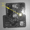
The following picture is a remote control panel car (Centrlock) device is disabled ... Upon detection it found that the surface coils marked rectangle white Open Circuit problem that there are no values on the coils or on the board.
I found another device of the same type works and I measured the resistance of these coils show that the following values the first 1 Ohm and the second 5.5 Ohm and the third 2.7 Ohm I do not know its value in Henry
Is there a way to know its value in Henry ??? Computationally
Is it possible to install coils that does not have the same tired resistance ??
And where I can find surface coils that have such ohmic values (I mean in any devices can have coils of this type)


بدون عنوان-2.jpg

thanks
 

Ylli

Jun 19, 2018
405
Joined
Jun 19, 2018
Messages
405
This is an remote control transmitter? Guessing the part you have labeled Hn43B is likely an encode, followed by a gated oscillator and a matching network/filter to the antenna. The surface mount inductors look to be 0805 (2012 metric) sized. You can not determine the inductance value from the DC resistance, and the value in a circuit like this is critical. Unless you can find a service manual for this device, the best suggestion would be to buy a new one.
 

mofth70

Aug 23, 2019
5
Joined
Aug 23, 2019
Messages
5
This is an remote control transmitter? Guessing the part you have labeled Hn43B is likely an encode, followed by a gated oscillator and a matching network/filter to the antenna. The surface mount inductors look to be 0805 (2012 metric) sized. You can not determine the inductance value from the DC resistance, and the value in a circuit like this is critical. Unless you can find a service manual for this device, the best suggestion would be to buy a new one.


Thank you and appreciation and respect
 

73's de Edd

Aug 21, 2015
3,622
Joined
Aug 21, 2015
Messages
3,622
Sir mofth70 . . . . .

That 'ole BLACK conformal coating, certainly hinders any board tracing and evaluation !

If needed later, what specific functions are tact switches 1-2 and 3 ? . . . Enable /Disable + Horn + Lights ?

As I am perceiving that board, the primary functioning brains and the digital processing of creating a serial digital output stream for each pushbutton function is occuring within the IC2 at the top.

I can't differentiate if the top of your YELLOW highlighted part is being a shiny case top, or just reflected light, from a BLACK surface. I suspect that whole device to be using SWIF technology, for creating the frequency stable aspect of the units RF transmitter, and is receiving that IC1's outputed code stream / burst input to modulate the RF..
Your cryptic Hn 43B marking is likely identifying the 433 mhz band / spectrum that the transmitter outputs on.

It then outputs its signal into the "325" beside it . . . . be it a transistor or MMIC to boost the RF level .
Then figure on a circuitry path to the closest of your WHITE mark ups, which is suspicioned, to be a coil with a companion series resonant cap to ground and the pair being a harmonic trap function.

Then the next two side by side WHITE mark up parallel resonant coils to the left, with their companion capacitors are passing the RF to the left to connect to the built in foil loop antenna .
It is encompassing about 1/2 of the left periphery of the circuit board. Starting at the end of the via to the right of tact SW3 and its extreme other end, is at the via near "5" marking, RF goes in near mid point at the SW2 silk screened marking.

The coils . . . .

Currently its the norm to have surface mount parts having magnetic susceptability, so that production line "bots" can handle them.
(And also ME, when I drop one into the carpet !)
I can see 3 Surface Mount resistors to the left of that " 325 ".
What you might try, is a small rod rare rarth magnet and get the feel of the attraction / pull upon one of those resistors.
Then check the difference, compared to one of your " coils ", as their powdered iron or ferrite attraction should be appreciably stronger.

Could your initial handling the "coils" or trying to scrape off their black coating be responsible for their demise to open circuits . . . . . Hmmmmmmmm ?

If all is as I surmise, you might try getting micro soldering iron in hand and surgically tin its tip to an ultra shiny tinned metal state.
Get some . . . 2 . . . .fine . . . bare copper AC wire copper strands of 2-3-4 mm length and pre tin both ends.
Make a center V or U bend to size to the width of a coil. Tweezer hold in the center and make a fast in and out surgical soldering of one lead, then the other.
That way, you have just jumpered the open coil.
Move to the other coil to the side and do the same.
The coil closest to the "325" can be left in an open state, should it be in thatt condition..
The other two side by side coils have to pass RF thru them on the route from transmitter output to the PCB's foil loop.
If either being open . . . . .. no transmitter RF can pass to the loop antenna.
Now, the unit will not have optimal filtering . . . . but RF should now pass.

Check out the unit very very close to the car, initially, to see if it responds.

73's de Edd . . . . .


Confidence is the feeling you have before you FULLY understand a situation.
 

mofth70

Aug 23, 2019
5
Joined
Aug 23, 2019
Messages
5
Sir mofth70 . . . . .

That 'ole BLACK conformal coating, certainly hinders any board tracing and evaluation !

If needed later, what specific functions are tact switches 1-2 and 3 ? . . . Enable /Disable + Horn + Lights ?

As I am perceiving that board, the primary functioning brains and the digital processing of creating a serial digital output stream for each pushbutton function is occuring within the IC2 at the top.

I can't differentiate if the top of your YELLOW highlighted part is being a shiny case top, or just reflected light, from a BLACK surface. I suspect that whole device to be using SWIF technology, for creating the frequency stable aspect of the units RF transmitter, and is receiving that IC1's outputed code stream / burst input to modulate the RF..
Your cryptic Hn 43B marking is likely identifying the 433 mhz band / spectrum that the transmitter outputs on.

It then outputs its signal into the "325" beside it . . . . be it a transistor or MMIC to boost the RF level .
Then figure on a circuitry path to the closest of your WHITE mark ups, which is suspicioned, to be a coil with a companion series resonant cap to ground and the pair being a harmonic trap function.

Then the next two side by side WHITE mark up parallel resonant coils to the left, with their companion capacitors are passing the RF to the left to connect to the built in foil loop antenna .
It is encompassing about 1/2 of the left periphery of the circuit board. Starting at the end of the via to the right of tact SW3 and its extreme other end, is at the via near "5" marking, RF goes in near mid point at the SW2 silk screened marking.

The coils . . . .

Currently its the norm to have surface mount parts having magnetic susceptability, so that production line "bots" can handle them.
(And also ME, when I drop one into the carpet !)
I can see 3 Surface Mount resistors to the left of that " 325 ".
What you might try, is a small rod rare rarth magnet and get the feel of the attraction / pull upon one of those resistors.
Then check the difference, compared to one of your " coils ", as their powdered iron or ferrite attraction should be appreciably stronger.

Could your initial handling the "coils" or trying to scrape off their black coating be responsible for their demise to open circuits . . . . . Hmmmmmmmm ?

If all is as I surmise, you might try getting micro soldering iron in hand and surgically tin its tip to an ultra shiny tinned metal state.
Get some . . . 2 . . . .fine . . . bare copper AC wire copper strands of 2-3-4 mm length and pre tin both ends.
Make a center V or U bend to size to the width of a coil. Tweezer hold in the center and make a fast in and out surgical soldering of one lead, then the other.
That way, you have just jumpered the open coil.
Move to the other coil to the side and do the same.
The coil closest to the "325" can be left in an open state, should it be in thatt condition..
The other two side by side coils have to pass RF thru them on the route from transmitter output to the PCB's foil loop.
If either being open . . . . .. no transmitter RF can pass to the loop antenna.
Now, the unit will not have optimal filtering . . . . but RF should now pass.

Check out the unit very very close to the car, initially, to see if it responds.

73's de Edd . . . . .


Confidence is the feeling you have before you FULLY understand a situation.


Thank you for your help and valuable information
Thank you very much
 

73's de Edd

Aug 21, 2015
3,622
Joined
Aug 21, 2015
Messages
3,622
Much better !
Now 2 of my suspected resistors, turned out to be ceramic compact SM capacitors.
Same board ?, but with the use of solvent ?
Hope that none creeped into the tact switches, or that they are resistant to what you used, if used selectively.
How about pulling the batteries and doing an ohms test across each switch, and then pressing for five tests of each switch.
That metal enclosure / shielding was EXACTLY what I was expecting, on that part.

Edd
 
Last edited:

mofth70

Aug 23, 2019
5
Joined
Aug 23, 2019
Messages
5
Much better !
Now 2 of my suspected resistors, turned out to be ceramic compact SM capacitors.
Same board ?, but with the use of solvent ?
Hope that none creeped into the tact switches, or that they are resistant to what you used, if used selectively.
How about pulling the batteries and doing an ohms test across each switch, and then pressing for five tests of each switch.
That metal enclosure / shielding was EXACTLY what I was expecting, on that part.

Edd


Thanks for your help
 
Top