Maker Pro
Maker Pro

Can a clock pendulum be slowed down by adding a resistor to the PSB?

BobK

Jan 5, 2010
7,682
Joined
Jan 5, 2010
Messages
7,682
I would think that a pendulum that swings at half the expected speed would look very unnatural. You might not like the effect even if you could achieve it.

Bob
 

R92024

Aug 8, 2015
9
Joined
Aug 8, 2015
Messages
9
I would think that a pendulum that swings at half the expected speed would look very unnatural. You might not like the effect even if you could achieve it.

Bob
I know what you mean, Bob, but I have experimented by slowing down a video... it looks unusual, but it's eye-catching, and in keeping with my product:
http://www.nowclock.com
 

hevans1944

Hop - AC8NS
Jun 21, 2012
4,880
Joined
Jun 21, 2012
Messages
4,880
I'm looking for advice, please. I’m a manufacturer, not an engineer, and not very technically minded, sorry!

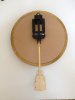
I manufacture and sell wall clocks that have a swinging pendulum. The pendulum mechanisms are made overseas and designed for the pendulum to swing approximately 60 times per minute.

I would like to slow down that swing to approximately 30 or even 20 swings per minute.
...
Maybe you should have sought the advice of an engineer or someone who is very technically minded... before you purchased a thousand of these pendulum movements from Asia. A pendulum is what it is. But that doesn't mean you can't work with the physics. Your pendulum mechanism in its current form has very little in the way of frictional loses, and almost zero windage losses, so the little coil is able to provide a "push" twice each cycle to add just enough energy to make up for these losses. But what would happen if you could increase those losses in a manner that would slow the pendulum down?

I am reminded of a triple-beam balance that I have. The balance consists of a lever arm with sliding weights that operate against the weight of objects in the weighing pan through a system of linkages and knife-edge pivots. To weigh something, you adjust the position of the sliding weights until the lever arm remains in a balanced horizontal position. Unfortunately, if the scale is nearly balanced, the lever arm will oscillate up and down about the horizontal position for a considerable period of time before finally stopping. To avoid this inconvenience, a metal tab is affixed to the end of the lever arm. The tab moves up and down with the lever arm between the poles of strong permanent magnet. The tab is made of a conductive, but non-magnetic, material such as copper or aluminum. The up and down motion of the lever arm near the balance position causes eddy currents to be induced in the metal tab by the magnetic poles. These eddy currents create their own magnetic field that opposes the up and down motion of the lever arm. The result is the up and down motion is slowed and rapidly damped.

I think a similar effect could be produced with your pendulum by attaching a curved copper or aluminum plate the extends to either side of the pendulum arm. If some powerful magnets are placed on opposite sides of this metal plate, when the pendulum swings the plate will pass across the poles of the magnet. This will induce a torque that will tend to slow the pendulum. You will probably need to increase the "push" the electromagnet provides to make up for the eddy current losses. And perhaps find someone who can solve the complex differential equations that describe the period of damped pendulum motion.

You can easily try this idea to see if it slows the period of the pendulum. Just glue a piece of copper strip thick enough to be self-supporting to the pendulum arm. Find a strong permanent magnet and glue it behind the pendulum rod so the copper strip passes over the magnet. The more magnets you use the more the motion will be dampened. You could try moving the pendulum bob by hand to measure the period, and later figure out how to replace the energy lost to the eddy currents.
 

duke37

Jan 9, 2011
5,364
Joined
Jan 9, 2011
Messages
5,364
@hevans1944
I do not believe than dropping the Q of this circuit will affect the frequency significantly. Of course much more drive power would be required.

A swinging weight above the pivot point has been tried. I am surprised that this made no difference to the frequency. It is 60 years since I derived the equation for a pendulum, I am not starting on the calculation of this configuration. Perhaps R92024 could do it?
 

hevans1944

Hop - AC8NS
Jun 21, 2012
4,880
Joined
Jun 21, 2012
Messages
4,880
@hevans1944
I do not believe than dropping the Q of this circuit will affect the frequency significantly. Of course much more drive power would be required.
...
Well, it shouldn't, but I was thinking of a forced pendulum oscillation which requires a lower Q to be effective. The problem is, the simple impulse provided by the electromagnetic "kicker" does not lend itself to the sinusoidal forcing torque described in the document at the linked site. Without considerably more sophistication in the drive mechanism, which would probably make the "clock" unaffordable, it is doubtful that reducing the period from 60 swings per minute to half or a third of that will be successful. Sounds to me like @R92024 needs a different mechanism to swing his "pendulum".
It is 60 years since I derived the equation for a pendulum, I am not starting on the calculation of this configuration. Perhaps R92024 could do it?
Well, it hasn't been quite that long for me, but I am in no mood to resurrect the trials and tribulations I encountered in learning how to solve differential equations, whether linear or not, simple or partial. All that stuff is done numerically now, rather than analytically, as I was taught, for that narrow sub-set of problems that have analytical solutions. Or you can purchase programs like MathCad if you aren't a computer geek or math whiz. But the OP has already stated he is not an engineer or someone who is very techinically minded, so I think the chances that he could do it are slim to none.

A swinging weight above the pivot point has been tried. I am surprised that this made no difference to the frequency.
I am surprised too. It should have made the oscillations faster since it apparently moved the center of gravity of the pendulum closer to the "knife edge" pivot axis. Or maybe the length was comparable to the original length from the pivot to the original pendulum bob.
 

duke37

Jan 9, 2011
5,364
Joined
Jan 9, 2011
Messages
5,364
The two weights are operating in opposition, when one is falling, the other is rising so the nett restoring force is smaller and the frequency will be less. Or am I wrong?
If the weights are the same and the pendulum is pivoted in the middle, there will be no restoring force and the frequency will be zero.
I am rather busy at the moment but I could take strip of wood with a hole in the middle and tie a weight on the top part at different distances from the pivot.
Whether a nail through a plywood hole will give low enough friction, I know not.
 

R92024

Aug 8, 2015
9
Joined
Aug 8, 2015
Messages
9
Hopefully these photos will load today, showing the pendulum mechanism higher on the back of the clock (not in the center, as I had before) allowing the pendulum rod to be longer, without appearing too long under the clock. So thank you for those suggestions!
 

Attachments

  • IMG_0680 (1).jpg
    IMG_0680 (1).jpg
    140.7 KB · Views: 96
  • IMG_0684.jpg
    IMG_0684.jpg
    136.8 KB · Views: 100

Alec_t

Jul 7, 2015
3,590
Joined
Jul 7, 2015
Messages
3,590
The two weights are operating in opposition, when one is falling, the other is rising so the nett restoring force is smaller and the frequency will be less. Or am I wrong?
The period of oscillation of a pendulum is independent of the pendulum mass, but depends on the distance of the centre of mass from the pivot, which is shortened by that dual mass arrangement and, as Hop said, should reduce the period (increase the frequency).
 

hevans1944

Hop - AC8NS
Jun 21, 2012
4,880
Joined
Jun 21, 2012
Messages
4,880
I think it should be obvious by now that there is no simple solution to the problem of increasing the period of a pendulum, other than to increase the distance between the bob and the pivot. Modifications to the electromagnetic device that keeps the bob moving in the presence of frictional losses will only affect the amplitude of the swing, not the period. OTOH, forced pendulum oscillations can lead down some pretty complicated pathways, including chaotic pendulum motion. It's too bad that @R92024 has "invested" in a thousand of these inexpensive pendulum movements, but simply mounting them higher on the back side of the "clock" face will not allow the period to increase very much... the period is proportional to the square root of the pendulum length... so increasing that length by a factor of four would be necessary to double the period.

With 20-20 hind-sight, this should have been obvious by simple examination of the period and length of the pendulum in a "grandfather" clock, whose period is two seconds: tick-tock-tick. The ticks and tocks are the noise of the escapement mechanism as it "bumps" the pendulum at the extremes of each swing to replace the energy lost to friction with energy released from the slowly falling weights. It appears that the el-cheapo pendulum was never intended to be part of a real clock mechanism: it is intended only for show, perhaps to be included as an accessory to a battery-powered quartz mechanism.

I like the idea that @R92024 has of eliminating the clock mechanism entirely.
 

duke37

Jan 9, 2011
5,364
Joined
Jan 9, 2011
Messages
5,364
The compound pendulum seems the way to go. Make a pendulum with a cross arm with a weight at each end. This could be hid behind the 'clock' face and will increase the moment of inertia.
There may be trouble with the pivot if made of plastic due to the increased loading.
 

R92024

Aug 8, 2015
9
Joined
Aug 8, 2015
Messages
9
There IS a solution - a Compound Pendulum.

A simple rod pivoted at its centre will not swing, but if the pivot point is shifted, it will.

http://farside.ph.utexas.edu/teaching/301/lectures/node141.html

Hello Ramussons,
Thank you for your reply, and my apologies for the very late reply. I didn't get notification of your post... but it's very interesting!
Unfortunately, the technical info in the 'compound pendulum' attachment is beyond my limited understanding... I have experimented with the 'cross arm' that Duke mentions, but so far no success in slowing the swing.
Photos attached.
Am I on the right lines?
Many thanks,
Richard
RicharIMG_0750.jpg IMG_0752.jpg
 
Top