Maker Pro
Maker Pro

Can 7.4V 1900maH battery positive lead fry Raspberry Pi if attached to ground GPIO pin?

Steve Peart

Sep 16, 2015
53
Joined
Sep 16, 2015
Messages
53
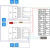
I fried my raspberry pi somehow recently while working on my custom motor circuit that uses 2 L298N's for controlling the motors in my project.

My source voltage comes from a 7.4V LiPo 1900maH Hobby Battery pack.

While testing, I think i may have accidentally crossed the positive lead from the battery pack to the ground directly, that is plugged into the ground GPIO pin on the raspberry pi.

Can this be the cause of the fried Raspberry Pi? I tried debugging other possible reasons for the failure but everything else checks out fine. Let me know if you would like more information to help me out.

I've already been bidding on replacement Pi's but it would be great to understand the problem to avoid making it happen again.

Also, how can I protect the Pi from damage caused by my circuit?

Thanks!
 

CDRIVE

Hauling 10' pipe on a Trek Shift3
May 8, 2012
4,960
Joined
May 8, 2012
Messages
4,960
Installing circuit protection is always a good idea. You can start by including a fuse in your circuit.

Chris
 

Harald Kapp

Moderator
Moderator
Nov 17, 2011
13,722
Joined
Nov 17, 2011
Messages
13,722
I think i may have accidentally crossed the positive lead from the battery pack to the ground directly
That wouldn't fry the controller. just drain a lot of current from the battery.
What could fry the controller is connecting the 7.4V directly to a GPIO pin. There are diodes from each pin to ground and Vcc to protect the pin from overvoltage. Without current limiting (e.g. a series resistor which you didn't have in place), a high current flows from the pin through the diodes to who knows where in the circuit. This is very likely to damage the controller.

You can start by including a fuse in your circuit.
A fuse will not help much here. By the time it blows the current will already have wreacked havoc on the circuit.
The L298 requires only a minimal input current (<= 100µA). A resistor in series between the GPIO and the L298's input can used to limit fault currents without noticeably influencing the normal operation. Assuming a voltage drop of e.g. 0.2V at 100µA makes for a 2kΩ resistor.
In case of erroneously applying 7.4V to the resistor, this limikts the fault current into the controller to 1mA...4mA, depending on the state of Vcc of the controller at that moment. This should be no issue for the Rasberry Pi as the GPIOs can source or sink up to 16mA.
Here is some more information on the Raspberry's GPIOs, scroll down to "Interfacing with GPIO pins".
 

CDRIVE

Hauling 10' pipe on a Trek Shift3
May 8, 2012
4,960
Joined
May 8, 2012
Messages
4,960
Yes Harald, I agree. I just think that when experimenters use high current batteries it would also be wise to fuse them. Though I think current limiting supplies are the cat's meow when experimenting.

In Steve's case (I'm not familiar with Raspberry) I thought he was referring (GPIO) to a power input jack. I now surmise it means "general pin in - out".

Cheers,
Chris
 

Nicholas Schlensky

Oct 7, 2015
9
Joined
Oct 7, 2015
Messages
9
I put 100R resistors in all io lines by reflex. You can replace them with a short, a higher value or a ferrite bead as req and is useful if you have to mod the board.
 

Steve Peart

Sep 16, 2015
53
Joined
Sep 16, 2015
Messages
53
So if/when the LiPo battery positive lead was crossing the ground line, then I WOULD be sending all that the battery has directly to the GND GPIO pin on the Raspberry Pi. I certainly plan to implement possibly some zener diodes on the parts that use input to the raspberry pi, but my only suspect is that the current and voltage of the battery was just too much for the RPi, even though it would have drained to a GND pin. Otherwise, I have no idea what popped and rendered the Raspberry Pi useless. I have read that the GPIO pins are totally unprotected (at least in my version of the RPi, the original B version with 256M RAM), I am just not a circuit expert and don't know if the GND pin and mistaken volts/amps going to it would cause any problems. The fuse idea makes sense, as well as the resistors, from what i can tell, my circuit is intact and unbroken, but the RPi itself is what croaked. I'd have preferred it the other way around, but now I am just trying to understand what went wrong so I don't make the same mistake on the next RPi.
 

BobK

Jan 5, 2010
7,682
Joined
Jan 5, 2010
Messages
7,682
You have not told us enough about this to answer your question. What is the - terminal of the battery connected to?

If you simply connected the + lead of the battery to the ground of the Rpi, then nothing would happen. If the - lead of the battery was connected to the same ground, your battery would drain quickly and heat up, but nothing would happen to the Rpi. If you had the - lead of the battery connected to the + power pin of the Rpi, that is a different story, likely it would kill the chip.

Bob
 

Harald Kapp

Moderator
Moderator
Nov 17, 2011
13,722
Joined
Nov 17, 2011
Messages
13,722
@Steve Peart : It helps alot when you show us the relevant part of your schematic (what is how connected to the Raspberry Pi).
You never connect a battery to an I/O pin without any sort of load or current limiting in between.
Typically you'd connect "-" of the battery to "gnd" of the Raspberry. "+" of the batter goes to the load to be switched by the Raspberry. Insert a simple driver stage in between to protect the Raspberry and to enable higher load currents.

sending all that the battery has directly to the GND GPIO pin on
There is no such thing as a "GND GPIO" pin. The Raspberry has a ground terminal (maybe more than one), labeled typically GND or GROUND. This is where usually the negative terminal of the power supply goes. It is the dommon reference for all voltages, therefore sometimes also called 0V.

A GPIO pin is a pin that can be used as Input or Output (it is General Purpose because it can be used in either direction).
In output mode, current will flow from the pin to GND when the output is logic high, from the pin to Vcc when the output is logic low.
In input mode, a very small (almost negligible) current will flow into the input pin. The relevant information is in the input voltage which shall be either logic high or logic low. Which voltages are logic high or low depends on the circuit. As the Raspberry uses 3.3V logic,logic levels are approximately:
Vin < 1V -> logic low
Vin > 2.3V -> logic high​
Any voltage above 3.3V can destroy the chip.
 

Steve Peart

Sep 16, 2015
53
Joined
Sep 16, 2015
Messages
53
Here's the schematic I put together in Photoshop, I have no clue how to use actual PCB design software. This is how I have everything wired up currently, the blue squares are screw terminals for the motors, the resistor for the LED is just an image for reference, the stripes on it aren't what im using there, and the RPi pin block on the right is actually a ribbon cable connector, as opposed to direct connections to the Pi, even though technically that does mean they do directly connect. The JST block under the RPi pin block is the connector to the RC Battery pack.

@Harald Kapp , when I said GND GPIO Pin, i meant the pins on the RPi block that are the ground pins, as opposed to the GND pins being actual IO.

What I think may have happened, is that the + lead on the JST connector crossed over the - lead of the LED since i didn't have the JST connector glued down and some of the wire was exposed. This is what i meant when I say that the + batter lead would have been grounded.

tank-pcb-png.22437


Is this better information? I appreciate your guys' help on this. If you could tell me where the protection parts of this circuit should go, I can revise this diagram and re-post to see if i've implemented it correctly.
 

Attachments

  • Tank-PCB.png
    Tank-PCB.png
    54.5 KB · Views: 253

Harald Kapp

Moderator
Moderator
Nov 17, 2011
13,722
Joined
Nov 17, 2011
Messages
13,722
as opposed to the GND pins being actual IO.
There are no GND pins being actual IO. Pins are either GND or IO, not both.

What I think may have happened, is that the + lead on the JST connector crossed over the - lead of the LED
That would have shorted the battery, but the Raspberry should not have been damaged.
What could have happened, if somehow the GND connection from the JST connector was connected to the Raspberry but not to the LED is, that the LED, seeing a high voltage on the cathode became conductive (reverse breakdown) and the high voltage was connected via the resistor to the 5V pin of the Raspberry. In that case a high current (depending on the value of the resistor) could have flown into 5V (which is not the intended mode of operation) and finding a way to GND within the Raspberry this current may have fried the little board.
 

Steve Peart

Sep 16, 2015
53
Joined
Sep 16, 2015
Messages
53
I suppose that's also possible, given the - lead of the battery was just as exposed as the + lead. I guess I'll go with that for now as the cause. Nothing else was loose on the board and other than crossing some lead with a screw driver on accident or something, it's the most likely case.

I also realize that the GND pin is not an IO pin, but that pin is part of the GPIO Pin header as a whole, i must have mixed words on that, but thanks for the clarification nonetheless.

As for my design, are there any other protections you guys would put in place? Once i get my new RPi (I may order two, just in case), I want to get right back to work on things.

Thanks!
-Steve
 
Top