Maker Pro
Maker Pro

Camera leveller

camerart

Aug 18, 2010
135
Joined
Aug 18, 2010
Messages
135
Hi,

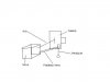
I am trying to make a Camera leveller, using dismantled Radio control Servos for the action and Opto couplers with Pendulums for the sensing.

The Servo Potentiometers are out of the case, and I need to know how to connect the Opto couplers to the Servos to give feedback.

The Opto couplers are: GP1S096HCZ0F.( I couldn't attach the PDF). And with my set-up give a variable output.

I hope I have explained it ok.

Thanks

Camerart.
 

NickS

Apr 6, 2010
367
Joined
Apr 6, 2010
Messages
367
I personally need more info. The isolator you listed is an photointerrupter like what is used for the scroll wheel in a mouse. I do not know what you are going to do with pendulums. Are you talking about physical swinging mass on a rope pendulums?

If so I am envisioning a precarious setup in which you are trying to swing a pendulum through a photointerrupter to tell your platform motors when to correct. But that will not tell you which way to correct it will only tell you when the mass is swinging. So I think I have misinterpreted your setup.
 

camerart

Aug 18, 2010
135
Joined
Aug 18, 2010
Messages
135
You have a little.

The opto couplers are tiny and so is the Pendulum. It only swings on one axis.

As the coupler tilts the Pendulum swings and give a nice swing from Min to Max resistance on the Meter.

I want to substitute the Servo Pot (I think is 5K) and put the Coupler in it's place.
 

NickS

Apr 6, 2010
367
Joined
Apr 6, 2010
Messages
367
You have a little.
The opto couplers are tiny and so is the Pendulum. It only swings on one axis.

As the coupler tilts the Pendulum swings and give a nice swing from Min to Max resistance on the Meter.
Ok so you are saying that the pendulum is an electronic device that changes impedance with position? That I understand. An analog level would indicate which direction you need to adjust. How you want to translate that to servo control is lost on me. What is the role of the photo interrupter in your scheme? See attached pic. These are for discrete encoding. Does your servo have an encoder wheel that fits in the slot of the opto? My RC servos require a PWM drive that telly them where to position. The opto you listed would be worthless to me and my servos. I could see a circuit that adjusts duty cycle based on the pendulum resistance being useful.

I want to substitute the Servo Pot (I think is 5K) and put the Coupler in it's place.
Again I fail to see how you intend directly replacing an analog device(5k POT) with a discrete device(opto). I guess you could turn to servo full scale or off but I am fairly confident that will not do a good job of fine leveling.

Do you have part numbers for your pendulum and your servos?

-Nick-
 

Attachments

  • PhotoInt.JPG
    PhotoInt.JPG
    21.7 KB · Views: 159

camerart

Aug 18, 2010
135
Joined
Aug 18, 2010
Messages
135
I hope I can explain it ok.

I made the Pendulum, which swings into and out of the Opto coupler GP1S096HCZ0F. giving a Min to Max resistance nicely. From this resistance change I need to produce a voltage.

The Servos are simple ones that have removable Pots. If a Pendulum is swung from the Servo Pot then it feeds back to the Servo circuit making it move forward or reverse. Because of friction, I found that the Pendulum has to be long, so I miniaturised the idea using the Opto coupler.

I need to remove the Pot and insert the Voltage from the Opto instead. which hopefully will do the same job.
 

davenn

Moderator
Sep 5, 2009
14,263
Joined
Sep 5, 2009
Messages
14,263
I hope I can explain it ok.

I made the Pendulum, which swings into and out of the Opto coupler GP1S096Z0FHC. giving a Min to Max resistance nicely. From this resistance change I need to produce a voltage.
The Servos are simple ones that have removable Pots. If a Pendulum is swung from the Servo Pot then it feeds back to the Servo circuit making it move forward or reverse. Because of friction, I found that the Pendulum has to be long, so I miniaturised the idea using the Opto coupler.
I need to remove the Pot and insert the Voltage from the Opto instead. which hopefully will do the same job.

an opto coupler is an enclosed (encapsulated device) you cant swing anything through it
you need a opto chopper like NickS stated. BUT there isnt going to be any change in resistance its only going to detect the making and breaking of the light beam between the LED and the photo transistor
that is ... no change in resistance

GP1S096HCZ0F is a photo-interrupter (opto-chopper)

Dave
 
Last edited:

camerart

Aug 18, 2010
135
Joined
Aug 18, 2010
Messages
135
Firstly, I'm sorry, but i have missed out 1/2 of the equation. The POT is the feedback balance for a 150 PWM signal, that I am going to inject on the Servo lead. Ooops.

The Pendulum that I have made does indeed cut the beam, and it should be used for Chopping as NickS says, but as it is set up in the way I have made it, does give a slow change instead of Chop.

It might be a better choice to alter the PWM signal instead of the Pot to put the Servo out of balance and make it go Backward and forward.
 

NickS

Apr 6, 2010
367
Joined
Apr 6, 2010
Messages
367
I am really having difficulty with this conceptually. Is there any way that you could draw a picture of how you envision this working. That may help us to help you.
 

camerart

Aug 18, 2010
135
Joined
Aug 18, 2010
Messages
135
Here is the attachment.

As the Camera tilts, and as the Pendulum 'box' is on the Camera, then the Pendulum swings and alters the resistance of the Coupler.

I want to use this to turn the Servo, either by changing the PWM side of the Balance or change the POT slider input to the Servo. This will level the Camera.
 

Attachments

  • Leveller.JPG
    Leveller.JPG
    9.6 KB · Views: 181

NickS

Apr 6, 2010
367
Joined
Apr 6, 2010
Messages
367
Where is the opto? That was the critical component I wanted to see interfaced with the pendulum.
 

camerart

Aug 18, 2010
135
Joined
Aug 18, 2010
Messages
135
As I am in a Library, and only have Paint to draw with, the mechanics of the Pendulum would be difficult for me.

Is it possible for you to look at the GP1S096HCZ0F PDF and read the spec regarding the resistance of on and off, then accept that I can slide from one to the other suitably, with my mechanics. If this is possible then can you tell me how I can use this variable resistance to substitute a 5K Servo POT, or change a PWM signal from say a 555 circuit to move each side of 150ms.

Cheers Camerart

I hope this is the easiest way for you.
 

NickS

Apr 6, 2010
367
Joined
Apr 6, 2010
Messages
367
I'm sorry, I am trying to be helpful on this but we are having some communication barrier that I can't seem to get over. I have looked over that datasheet repeatedly and there is no spec for on/off resistance(the attached pic shows all operating specifications). The only place in that datasheet I see that resistance is mentioned is in regard to impulse response vs the load resistance.

That opto functions like this. When you are forward biasing the LED it emits light through the channel(assuming that nothing is blocking the channel) it reached the photo transistor and works as a base current to bias the transistor thus turning it on. If you block the channel then the transistor turns off. It is more like a light switch than a POT or variable resistance. Sure your wall light switch has an on resistance of uOhms and an off resistance of MOhms but no one talks about it like that because it is just on or off. Your opto will behave similar. it will either turn the transistor on or off. If you did have that output rigged to a servo control I imagine it would fly from full scale right to full scale left(~300deg in one step). It is hard to imagine that as what you are looking for. You really need something that can span a range of resistance values. For the opto you have selected to work for a swept range you would involve taking it outside of its design parameters. You would have to find a way to reduce the photons through the channel without breaking the flow entirely.

Does that make sense?
 

Attachments

  • opto.JPG
    opto.JPG
    28.9 KB · Views: 108

camerart

Aug 18, 2010
135
Joined
Aug 18, 2010
Messages
135
Hi NickS,

'Communications barrier', the story of my life!!

Thank you for making the effort.

I wander through life inventing things, that are usually difficult to achieve. (This isn't intentional, I can assure you) Having said that I usually get them working, though.

The Pendulum does cut the light, in a similar way to the slotted wheel does, but if you imagine the wheel moving very precisely and slowly, the change from Off to On is not like a switch, but gradual. I can hold my contraption at On, Off and 1/2 way in between, and it it only needs to move a degree or so. This is what I was aiming for, the other simple levelling electronics I could find, could only manage to show change after 'say' 10-20 degrees.

As mentioned before, I have removed the Servo Pot to outside the Servo, and if a Pendulum is place on the Pot spindle, it acts, just as I want it to do, but the Pendulum must be quite long, say 3-4 inches, to overcome friction. This is inconvenient for use, and is why I tried a different way.

So, if we try a 555 square wave circuit, set to 150ms, I assume this will hold a normal Servo (as manufactured) to the middle of it's sweep?????

If this is so, then is it possible to interfere, with the balance using the resistance change of the Coupler to move it each side of 150ms. I'm sure this would work???

In my head this seems logical, but converting this into electronics, for me would be a nightmare, this is why I need help, and I'm grateful for any, thanks again.

C.
 

camerart

Aug 18, 2010
135
Joined
Aug 18, 2010
Messages
135
P.S. NickS,

I re-read you message.

Say the OPTO is on/off, with no in between, and the Servo does switch one way then the other, if you look at my Sketch, you will see that as soon the Servo moves the Camera (and Pendulum) it would reverse, so I imagine it would oscillate 1 degree up/down, but be almost upright. If this was possible, we are nearly there. I can switch the whole thing on and off just before triggering the Camera.
 

NickS

Apr 6, 2010
367
Joined
Apr 6, 2010
Messages
367
Ok, I was afraid that was what you were trying to do. For the sake of concept lets say you are able to get a consistent range. How do you know if the servo will correct right or left. It doesn't matter if your pendulum swings 5 degrees right or 5 degrees left of center the output will be the same and one direction may pull the base into level but the other direction will diverge.

Second. Since you are operating beyond what the device was intended for you will have widely varying results from device to device. No big deal if this is a one off. But if you plan on any sort of production it will be a nightmare to try to calibrate each one.

Now as for the 555 with varying duty cycle that is not a perfect solution either. But it is slightly more intuative. If to place a 5k POT in place of the two resistors(R1, R2) with the sweeper to the discharge pin then over a small range of the sweeper you will see approximately what you want but in reality the frequency/duty cycle accuracy will not be good enough. Anyway this still would not solve the directionality issue.

I would recommend a solid state accelerometer for this project. it is small and low power plus it gives you directionality. Now translating that to your servos is still the trick. I would recommend a micro controller myself. You could read the levels off the accelerometer and output the proper duty cycle change accordingly. Plus you would have the ability to set up a proper PID feedback path for reliable control.
 

Attachments

  • 555.JPG
    555.JPG
    19.6 KB · Views: 111
Last edited:

NickS

Apr 6, 2010
367
Joined
Apr 6, 2010
Messages
367
hmm, I was assuming you would want the pendulum centered when the base was centered but actually if it was partially breaking the beam at platform center that could give you directionality.
ie
Full Beam----3/4Beam-----1/2Beam-----1/4Beam-----No Beam
-150Deg___-75Deg____0Deg______+75Deg___+150Deg

But I still think the accelerometer and uController are a better fit.
 
Last edited:

camerart

Aug 18, 2010
135
Joined
Aug 18, 2010
Messages
135
I don't understand your terminology "may pull the base into level but the other direction will diverge. "

I will look into Accelerometers, are they as responsive? I hoped to make a simple analogue circuit if possible.

My Opto arrangement gives full on to full off in approx 2 Degrees.

I think I follow what you are saying, regarding the PWM side of the Servo balance. So I doubt this would work.

If then we look at the POT side of the Servo Balance. If this is out of balance, the amount the Pot is out gives the Servo correction speed. If we could get the Opto to put the Pot side out of balance a little each side of Centre then hopefully the Opto should correct the angle ok.

Does this sound more viable?
 

(*steve*)

¡sǝpodᴉʇuɐ ǝɥʇ ɹɐǝɥd
Moderator
Jan 21, 2010
25,510
Joined
Jan 21, 2010
Messages
25,510
The question Nick asks is how your circuit will know the difference if tipped to the left or right from level.

your sensor may be able to detect "level", but how does it detect which way out of level you are?
 

camerart

Aug 18, 2010
135
Joined
Aug 18, 2010
Messages
135
Hi,

I am limited in my electronics skills.

I can hold the Pendulum fully on, fully off, and anywhere in between, according to my Resistance meter, so I thought that there must be some way of putting one side (PWM) or the other side (POT) of a Servo slightly out of balance, the Servo would move one way or the other.

The full on to full off has been adjusted to approx 2 degrees, for sensitivity.

It is difficult to explain without seeing it in action, but I hope this is clearer for you.
 

NickS

Apr 6, 2010
367
Joined
Apr 6, 2010
Messages
367
Camerart-- I have not used servos like you have. It sound like your the POT you keep mentioning is using the center tap as a control line voltage. Is that correct? So a varying DC level translates the position of the arm. If this is correct then the next part is (what you have been asking for all along). may be an iterative process unless you can tell us the model number on that servo.

Steve-- I think I figured out how he gets directionality. It is not a good idea in my judgment but it might work in some cases. He basically sets his balance point to where the pendulum is exactly half way through the beam. So if he blocks more it moves left and if he blocks less it moves right. But honestly I still don't think this will work. I am pretty sure this thing is going to start oscillation and never be able to recover. I think this because he has stated that 2deg of pendulum swing equates to full scale on the servo which I think should be about 300deg. So once this thing starts to correct the pendulum is going to be bouncing all over the place only briefly passing through the beam as it swings around. What do you think? I think the only thing that could save it is if we can block the servo range into a small frame of motion. I think it would have to follow the 2deg range on the pendulum and at that point it may not even be useful.
 
Top