I'm planning my pH controller now.
It will be an arduino microcontroller with an analog input 0-5V.
Due to the high impedans in the pH circuit and the low voltage i cant connect it directly.
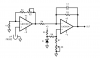
I have taken a look at national semiconductor reference design as shown in attachment.
And that seems ok for me.
But since the pH probe gives out - voltage under pH 7 and + voltage with pH over 7 i must somehow convert that voltage into a 0-5v signal.
Any idea how i could do that ?
It will be an arduino microcontroller with an analog input 0-5V.
Due to the high impedans in the pH circuit and the low voltage i cant connect it directly.
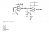
I have taken a look at national semiconductor reference design as shown in attachment.
And that seems ok for me.
But since the pH probe gives out - voltage under pH 7 and + voltage with pH over 7 i must somehow convert that voltage into a 0-5v signal.
Any idea how i could do that ?