Efficiency test completed, with disappointing results.
In the absence of any nice tools or probes, I simply connected a brand new Duracell 9V battery (a known capacity) to the chip, then used the output to charge my phone. My phone records mA data and battery % in a CSV file, which I can then integrate to find the total power output by the circuit.
In theory, this would work great. In reality, it either didn't work or my circuit is FUBAR.
CAVEAT:
This is just me, stabbing around with numbers and doing what seems logical. I don't know if what I'm doing is correct, accurate or even wise. But I'm trying!
With data this radical, I'm going to run more tests to see if I can confirm the results.
I tested the battery, fresh out of the box. 9.25V.
Before I disconnected the circuit, the working voltage left was 6.5V.
Simple math implies that the battery's average in-use voltage was 7.875V.
The next morning, the 9V battery had recovered back up to 8.4V. (Just in case you cared)
The average charging rate was a measly 260mA.
260mA at 5V transforms into into 1300mW.
At 7.875V, 1300mW transforms into 165mA.
The ∑mA given to the phone is 134.9mAh.
134.9mAh at 5V transforms into 674.5mWh.
At 7.875V, 674.5mWh transforms into 85.65mAh.
At 100mA, a 9V Coppertop should output a little over 300mAh (
source).
85/300 = 28.5% efficiency! Horrifying.
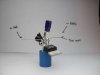
Oh, by the way. Photos attached.
Here's the CSV data, in case you're interested:
Code:
DATE | TIME | mA | % | V | TEMP | ASLEEP | ???
2011/07/20|19:30:10|-3mA|16%|3679mV|32.5ºC|2|2
*** Charging begins.
2011/07/20|19:31:10|567mA|16%|3679mV|32.5ºC|2|1
2011/07/20|19:32:10|480mA|17%|3776mV|32.3ºC|0|1
2011/07/20|19:33:10|472mA|18%|3776mV|32.1ºC|0|1
2011/07/20|19:34:10|465mA|18%|3776mV|32.1ºC|0|1
2011/07/20|19:35:10|271mA|18%|3776mV|32.1ºC|0|1
2011/07/20|19:36:10|262mA|19%|3747mV|31.2ºC|0|1
2011/07/20|19:37:10|257mA|19%|3747mV|31.2ºC|0|1
2011/07/20|19:38:10|261mA|20%|3762mV|30.6ºC|0|1
2011/07/20|19:39:10|258mA|20%|3762mV|30.6ºC|0|1
2011/07/20|19:40:10|257mA|20%|3762mV|30.6ºC|0|1
2011/07/20|19:41:10|255mA|20%|3762mV|30.6ºC|0|1
2011/07/20|19:42:10|254mA|21%|3771mV|30.0ºC|0|1
2011/07/20|19:43:10|249mA|21%|3771mV|30.0ºC|0|1
2011/07/20|19:44:10|250mA|21%|3771mV|30.0ºC|0|1
2011/07/20|19:45:10|248mA|22%|3781mV|29.6ºC|0|1
2011/07/20|19:46:10|247mA|22%|3781mV|29.6ºC|0|1
2011/07/20|19:47:10|241mA|22%|3781mV|29.6ºC|0|1
2011/07/20|19:48:10|238mA|22%|3781mV|29.6ºC|0|1
2011/07/20|19:49:10|242mA|23%|3791mV|29.2ºC|0|1
2011/07/20|19:50:10|240mA|23%|3791mV|29.2ºC|0|1
2011/07/20|19:51:10|239mA|23%|3791mV|29.2ºC|0|1
2011/07/20|19:52:10|238mA|24%|3796mV|29.0ºC|0|1
2011/07/20|19:53:10|233mA|24%|3796mV|29.0ºC|0|1
2011/07/20|19:54:10|228mA|24%|3796mV|29.0ºC|0|1
2011/07/20|19:55:10|233mA|25%|3806mV|28.7ºC|0|1
2011/07/20|19:56:10|231mA|25%|3806mV|28.7ºC|0|1
2011/07/20|19:57:10|230mA|25%|3806mV|28.7ºC|0|1
2011/07/20|19:58:10|224mA|25%|3806mV|28.7ºC|0|1
2011/07/20|19:59:10|163mA|26%|3767mV|28.5ºC|0|1
2011/07/20|20:00:10|59mA|26%|3767mV|28.5ºC|0|1
2011/07/20|20:01:10|2mA|26%|3767mV|28.5ºC|0|1
*** Charging ends.
2011/07/20|20:02:10|0mA|26%|3767mV|28.5ºC|0|1
2011/07/20|20:03:10|-4mA|26%|3767mV|28.5ºC|0|1
2011/07/20|20:04:10|-14mA|26%|3767mV|28.5ºC|0|1
2011/07/20|20:05:10|-10mA|26%|3767mV|28.5ºC|0|1
2011/07/20|20:06:10|-10mA|26%|3767mV|28.5ºC|0|1
2011/07/20|20:07:10|-9mA|26%|3767mV|28.5ºC|0|1
2011/07/20|20:08:10|-13mA|26%|3767mV|28.5ºC|0|1
2011/07/20|20:09:10|-17mA|26%|3767mV|28.5ºC|0|1
2011/07/20|20:10:10|-20mA|26%|3767mV|28.5ºC|0|1
2011/07/20|20:11:10|-11mA|26%|3767mV|28.5ºC|0|1
2011/07/20|20:12:10|-12mA|26%|3767mV|28.5ºC|0|1
2011/07/20|20:13:10|-14mA|26%|3767mV|28.5ºC|0|1
2011/07/20|20:14:10|-18mA|26%|3767mV|28.5ºC|0|1
2011/07/20|20:15:10|-30mA|25%|3762mV|27.8ºC|0|1
2011/07/20|20:16:10|-21mA|25%|3762mV|27.8ºC|0|1
2011/07/20|20:17:10|-20mA|25%|3762mV|27.8ºC|0|1
2011/07/20|20:18:10|-23mA|25%|3762mV|27.8ºC|0|1
2011/07/20|20:19:10|-27mA|25%|3762mV|27.8ºC|0|1
2011/07/20|20:20:10|-34mA|25%|3762mV|27.8ºC|0|1
2011/07/20|20:21:10|-28mA|25%|3762mV|27.8ºC|0|1
2011/07/20|20:22:10|-26mA|25%|3762mV|27.8ºC|0|1
2011/07/20|20:23:10|-29mA|25%|3762mV|27.8ºC|0|1
2011/07/20|20:24:10|-33mA|25%|3762mV|27.8ºC|0|1
2011/07/20|20:25:10|-35mA|25%|3762mV|27.8ºC|0|1
2011/07/20|20:26:10|-35mA|25%|3762mV|27.8ºC|0|1
2011/07/20|20:27:10|-38mA|25%|3762mV|27.8ºC|0|1
2011/07/20|20:28:10|-32mA|25%|3762mV|27.8ºC|0|1
2011/07/20|20:29:10|-33mA|25%|3762mV|27.8ºC|0|1
2011/07/20|20:30:10|-36mA|25%|3762mV|27.8ºC|0|1
2011/07/20|20:31:10|-47mA|25%|3762mV|27.8ºC|0|1
2011/07/20|20:32:10|-39mA|25%|3762mV|27.8ºC|0|1
2011/07/20|20:33:10|-47mA|25%|3762mV|27.8ºC|0|1
2011/07/20|20:34:10|-39mA|25%|3762mV|27.8ºC|0|1
2011/07/20|20:35:10|-43mA|25%|3762mV|27.8ºC|0|1
2011/07/20|20:36:10|-45mA|25%|3762mV|27.8ºC|0|1
2011/07/20|20:37:10|-44mA|25%|3762mV|27.8ºC|0|1
2011/07/20|20:38:10|-48mA|25%|3762mV|27.8ºC|0|1
2011/07/20|20:39:10|-41mA|25%|3762mV|27.8ºC|0|1
2011/07/20|20:40:10|-41mA|25%|3762mV|27.8ºC|0|1
2011/07/20|20:41:10|-43mA|25%|3762mV|27.8ºC|0|1
2011/07/20|20:42:10|-46mA|25%|3762mV|27.8ºC|0|1
2011/07/20|20:43:10|-45mA|24%|3737mV|27.2ºC|0|1
2011/07/20|20:44:10|-42mA|24%|3737mV|27.2ºC|0|1
2011/07/20|20:45:10|-43mA|24%|3737mV|27.2ºC|0|1
2011/07/20|20:46:10|-44mA|24%|3737mV|27.2ºC|0|1
2011/07/20|20:47:10|-48mA|24%|3737mV|27.2ºC|0|1
2011/07/20|20:48:10|-48mA|24%|3737mV|27.2ºC|0|1
2011/07/20|20:49:10|-61mA|24%|3737mV|27.2ºC|0|1
2011/07/20|20:50:10|-45mA|24%|3737mV|27.2ºC|0|1
2011/07/20|20:51:10|-46mA|24%|3737mV|27.2ºC|0|1
2011/07/20|20:52:10|-46mA|24%|3737mV|27.2ºC|0|1
2011/07/20|20:53:10|-49mA|24%|3737mV|27.2ºC|0|1
2011/07/20|20:54:10|-54mA|24%|3737mV|27.2ºC|0|1
2011/07/20|20:55:10|-46mA|24%|3737mV|27.2ºC|0|1
2011/07/20|20:56:10|-47mA|23%|3728mV|27.1ºC|0|1
2011/07/20|20:57:10|-48mA|23%|3728mV|27.1ºC|0|1
2011/07/20|20:58:10|-51mA|23%|3728mV|27.1ºC|0|1
2011/07/20|20:59:10|-53mA|23%|3728mV|27.1ºC|0|1
2011/07/20|21:00:10|-48mA|23%|3728mV|27.1ºC|0|1
2011/07/20|21:01:10|-49mA|23%|3728mV|27.1ºC|0|1
2011/07/20|21:02:10|-49mA|23%|3728mV|27.1ºC|0|1
2011/07/20|21:03:10|-53mA|23%|3728mV|27.1ºC|0|1
2011/07/20|21:04:10|-58mA|23%|3728mV|27.1ºC|0|1
2011/07/20|21:05:10|-50mA|23%|3728mV|27.1ºC|0|1
2011/07/20|21:06:10|-50mA|23%|3728mV|27.1ºC|0|1
2011/07/20|21:07:10|-50mA|23%|3728mV|27.1ºC|0|1
2011/07/20|21:08:10|-50mA|23%|3728mV|27.1ºC|0|1
2011/07/20|21:09:10|-52mA|23%|3728mV|27.1ºC|0|1
2011/07/20|21:10:10|-56mA|23%|3728mV|27.1ºC|0|1
2011/07/20|21:11:10|-51mA|23%|3728mV|27.1ºC|0|1
2011/07/20|21:12:10|-51mA|23%|3728mV|27.1ºC|0|1
2011/07/20|21:13:10|-51mA|23%|3728mV|27.1ºC|0|1
2011/07/20|21:14:10|-56mA|23%|3728mV|27.1ºC|0|1
2011/07/20|21:15:10|-61mA|22%|3718mV|27.0ºC|0|1
2011/07/20|21:16:10|-53mA|22%|3718mV|27.0ºC|0|1
2011/07/20|21:17:10|-50mA|22%|3718mV|27.0ºC|0|1
2011/07/20|21:18:10|-53mA|22%|3718mV|27.0ºC|0|1
2011/07/20|21:19:10|-55mA|22%|3718mV|27.0ºC|0|1
2011/07/20|21:20:10|-61mA|22%|3718mV|27.0ºC|0|1
2011/07/20|21:21:10|-53mA|22%|3718mV|27.0ºC|0|1
2011/07/20|21:22:10|-53mA|22%|3718mV|27.0ºC|0|1
2011/07/20|21:23:10|-53mA|22%|3718mV|27.0ºC|0|1
2011/07/20|21:24:10|-58mA|22%|3718mV|27.0ºC|0|1
2011/07/20|21:25:10|-59mA|21%|3713mV|27.0ºC|0|1
2011/07/20|21:26:10|-59mA|21%|3713mV|27.0ºC|0|1
2011/07/20|21:27:10|-58mA|21%|3713mV|27.0ºC|0|1
2011/07/20|21:28:10|-54mA|21%|3669mV|27.0ºC|2|2
2011/07/20|21:29:10|-204mA|21%|3669mV|27.0ºC|1|0
2011/07/20|21:30:10|-74mA|21%|3674mV|27.0ºC|2|2
2011/07/20|21:31:10|-219mA|21%|3679mV|27.1ºC|2|2
2011/07/20|21:32:10|-220mA|21%|3679mV|27.1ºC|2|0
2011/07/20|21:33:10|-2mA|21%|3679mV|27.1ºC|0|0
2011/07/20|21:34:10|-2mA|21%|3679mV|27.1ºC|0|0
2011/07/20|21:35:10|-2mA|21%|3679mV|27.1ºC|0|0
2011/07/20|21:36:10|-2mA|21%|3679mV|27.1ºC|0|0
2011/07/20|21:37:10|-2mA|21%|3679mV|27.1ºC|0|0
2011/07/20|21:38:10|-2mA|21%|3679mV|27.1ºC|0|0
2011/07/20|21:39:10|-31mA|20%|3708mV|26.8ºC|0|0
2011/07/20|21:40:10|-7mA|20%|3708mV|26.8ºC|0|0
2011/07/20|21:41:10|-9mA|20%|3708mV|26.8ºC|0|0
2011/07/20|21:42:10|-9mA|20%|3708mV|26.8ºC|0|0
*** I suspect this is the phone entering 'hibernate mode'
2011/07/20|21:43:10|-1mA|20%|3708mV|26.8ºC|0|0
2011/07/20|21:44:10|-1mA|20%|3708mV|26.8ºC|0|0
2011/07/20|21:45:10|-1mA|20%|3708mV|26.8ºC|0|0
2011/07/20|21:46:10|-1mA|20%|3708mV|26.8ºC|0|0
2011/07/20|21:47:10|-1mA|20%|3708mV|26.8ºC|0|0
2011/07/20|21:48:10|-1mA|20%|3708mV|26.8ºC|0|0
2011/07/20|21:49:10|-1mA|20%|3708mV|26.8ºC|0|0
2011/07/20|21:50:10|-1mA|20%|3708mV|26.8ºC|0|0
2011/07/20|21:51:10|-1mA|20%|3708mV|26.8ºC|0|0
2011/07/20|21:52:10|-1mA|20%|3708mV|26.8ºC|0|0
2011/07/20|21:53:10|-1mA|20%|3708mV|26.8ºC|0|0
2011/07/20|21:54:10|-51mA|20%|3708mV|26.8ºC|0|0
2011/07/20|21:55:10|-9mA|20%|3708mV|26.8ºC|0|0
2011/07/20|21:56:10|-9mA|20%|3708mV|26.8ºC|0|0
2011/07/20|21:57:10|-9mA|20%|3708mV|26.8ºC|0|0
2011/07/20|21:58:10|-1mA|20%|3708mV|26.8ºC|0|0
2011/07/20|21:59:10|-5mA|20%|3708mV|26.8ºC|0|0
2011/07/20|22:00:10|-1mA|20%|3708mV|26.8ºC|0|0
2011/07/20|22:01:11|-1mA|20%|3708mV|26.8ºC|0|0
2011/07/20|22:02:10|-1mA|20%|3708mV|26.8ºC|0|0
2011/07/20|22:03:10|-1mA|20%|3708mV|26.8ºC|0|0
2011/07/20|22:04:10|-1mA|20%|3708mV|26.8ºC|0|0
2011/07/20|22:05:10|-1mA|20%|3708mV|26.8ºC|0|0
2011/07/20|22:06:10|-1mA|20%|3708mV|26.8ºC|0|0
2011/07/20|22:07:10|-1mA|20%|3708mV|26.8ºC|0|0
2011/07/20|22:08:10|-1mA|20%|3708mV|26.8ºC|0|0
2011/07/20|22:09:10|-14mA|20%|3708mV|26.8ºC|0|0
2011/07/20|22:10:10|-8mA|20%|3708mV|26.8ºC|0|0
2011/07/20|22:11:10|-8mA|20%|3708mV|26.8ºC|0|0
2011/07/20|22:12:10|-1mA|20%|3708mV|26.8ºC|0|0
2011/07/20|22:13:10|-1mA|20%|3708mV|26.8ºC|0|0
2011/07/20|22:14:10|-1mA|20%|3708mV|26.8ºC|0|0
2011/07/20|22:15:10|-1mA|20%|3708mV|26.8ºC|0|0
2011/07/20|22:16:10|-1mA|20%|3708mV|26.8ºC|0|0
2011/07/20|22:17:10|-1mA|20%|3708mV|26.8ºC|0|0
2011/07/20|22:18:10|-1mA|20%|3708mV|26.8ºC|0|0
2011/07/20|22:19:10|-1mA|20%|3708mV|26.8ºC|0|0
2011/07/20|22:20:10|-1mA|20%|3708mV|26.8ºC|0|0
2011/07/20|22:21:10|-1mA|20%|3708mV|26.8ºC|0|0
2011/07/20|22:22:10|-1mA|20%|3708mV|26.8ºC|0|0
2011/07/20|22:23:10|-1mA|20%|3708mV|26.8ºC|0|0
2011/07/20|22:24:10|-10mA|20%|3708mV|26.8ºC|0|0
2011/07/20|22:25:10|-14mA|20%|3708mV|26.8ºC|0|0
2011/07/20|22:26:10|-18mA|20%|3708mV|26.8ºC|0|0
2011/07/20|22:27:10|-1mA|20%|3708mV|26.8ºC|0|0
2011/07/20|22:28:10|-1mA|20%|3708mV|26.8ºC|0|0
2011/07/20|22:29:10|-1mA|20%|3708mV|26.8ºC|0|0
2011/07/20|22:30:10|-1mA|20%|3708mV|26.8ºC|0|0
2011/07/20|22:31:10|-1mA|20%|3708mV|26.8ºC|0|0
2011/07/20|22:32:10|-1mA|20%|3708mV|26.8ºC|0|0
2011/07/20|22:33:10|-1mA|20%|3708mV|26.8ºC|0|0
2011/07/20|22:34:10|-1mA|20%|3708mV|26.8ºC|0|0
2011/07/20|22:35:10|-1mA|20%|3708mV|26.8ºC|0|0
2011/07/20|22:36:10|-1mA|20%|3708mV|26.8ºC|0|0
2011/07/20|22:37:10|-1mA|20%|3708mV|26.8ºC|0|0
2011/07/20|22:38:10|-1mA|20%|3708mV|26.8ºC|0|0
2011/07/20|22:39:10|-13mA|20%|3708mV|26.8ºC|0|0
2011/07/20|22:40:10|-7mA|20%|3708mV|26.8ºC|0|0
2011/07/20|22:41:10|-10mA|20%|3708mV|26.8ºC|0|0
2011/07/20|22:42:10|-10mA|20%|3708mV|26.8ºC|0|0
2011/07/20|22:43:10|-1mA|20%|3708mV|26.8ºC|0|0
2011/07/20|22:44:10|-1mA|20%|3708mV|26.8ºC|0|0
2011/07/20|22:45:10|-1mA|20%|3708mV|26.8ºC|0|0
2011/07/20|22:46:10|-1mA|20%|3708mV|26.8ºC|0|0
2011/07/20|22:47:10|-1mA|20%|3708mV|26.8ºC|0|0
2011/07/20|22:48:10|-2mA|20%|3708mV|26.8ºC|0|0
2011/07/20|22:49:10|-1mA|20%|3708mV|26.8ºC|0|0
2011/07/20|22:50:10|-1mA|20%|3708mV|26.8ºC|0|0
2011/07/20|22:51:10|-2mA|20%|3708mV|26.8ºC|0|0
2011/07/20|22:52:10|-1mA|20%|3708mV|26.8ºC|0|0
2011/07/20|22:53:10|-1mA|20%|3708mV|26.8ºC|0|0
2011/07/20|22:54:10|-13mA|20%|3708mV|26.8ºC|2|0
2011/07/20|22:55:54|-8mA|20%|3708mV|26.8ºC|2|0
2011/07/20|22:56:10|-8mA|20%|3708mV|26.8ºC|0|0
2011/07/20|22:57:10|-8mA|20%|3708mV|26.8ºC|0|0
*** I turn on the phone and examine it.
2011/07/20|22:58:10|-186mA|20%|3708mV|26.8ºC|2|0
2011/07/20|22:59:36|-96mA|20%|3708mV|26.8ºC|2|0
2011/07/20|23:00:10|-8mA|19%|3698mV|25.5ºC|2|4
2011/07/20|23:01:10|-178mA|19%|3664mV|25.7ºC|1|2
2011/07/20|23:02:10|-193mA|19%|3659mV|26.0ºC|1|2
2011/07/20|23:03:10|-201mA|19%|3654mV|26.2ºC|1|
*** The phone is now plugged into a charger.
2011/07/20|23:04:10|449mA|19%|3654mV|26.2ºC|1|1
2011/07/20|23:05:10|566mA|20%|3820mV|27.0ºC|2|1
2011/07/20|23:06:10|568mA|20%|3820mV|27.0ºC|0|1
2011/07/20|23:07:10|567mA|21%|3840mV|27.2ºC|0|1
2011/07/20|23:08:10|564mA|22%|3850mV|27.5ºC|0|1
2011/07/20|23:09:10|566mA|23%|3855mV|27.5ºC|0|1
2011/07/20|23:10:10|566mA|23%|3855mV|27.5ºC|0|1
2011/07/20|23:11:10|564mA|24%|3864mV|27.5ºC|0|1
2011/07/20|23:12:10|565mA|24%|3864mV|27.5ºC|0|1
2011/07/20|23:13:10|565mA|25%|3874mV|27.7ºC|0|1
2011/07/20|23:14:10|564mA|26%|3884mV|27.7ºC|0|1
2011/07/20|23:15:10|563mA|27%|3889mV|27.7ºC|0|1
2011/07/20|23:16:10|564mA|27%|3889mV|27.7ºC|0|1
2011/07/20|23:17:10|561mA|28%|3894mV|27.7ºC|0|1
 n time", the current can not rise as high. This will typically mean the SMPS has to operate at a lower frequency to permit longer ON times (This is not strictly true, but it does affect transient response).