Maker Pro
Maker Pro

Buck convertors

JohnP

Oct 22, 2016
31
Joined
Oct 22, 2016
Messages
31
Can I run 2 Buck convertors from 1 transformer. I wish to create a power supply that can handle 8.88A at 27V. I cannot find an Ammeter that will handle mA to this level. I can find on Amazon a 5 digit ammeter for 3A. Can I use a V & A 30V 10A meter from one Buck V & A variable convertor and another Buck convertor with current and voltage control for the 3A meter.
To sum up - 2 separate power supplies with 1 transformer.
 

(*steve*)

¡sǝpodᴉʇuɐ ǝɥʇ ɹɐǝɥd
Moderator
Jan 21, 2010
25,510
Joined
Jan 21, 2010
Messages
25,510
Your question is not very clear.

Sure, you can run 2 buck converters from a single power source. However, from here on your explanation gets very hard to follow.

What is your "transformer"? Is it literally a transformer, or is it some sort of DC power supply? If it is the former, you will need to rectify and filter the output. In either case, it would be useful for you to tell us the specs.

Your inability to get ammeters is surely not the reason you want 2 buck converters, is it?

What is the load you're driving. What voltage and what current?

Please try to tell us what you want to achieve rather than how you think you will achieve it.
 

JohnP

Oct 22, 2016
31
Joined
Oct 22, 2016
Messages
31
Thanks for the rapid reply. I'm rather new to this.
I have a toroidal transformer with 2 x18V outputs at 4.44A each. They are connected to give 18V at 8.88A. After bridge rectifier and 9,900uF 100V capacitors the voltage is 27.3V.

I wish to be able to control the current to within a few mA and the voltage to within 0.1 V. However this need only be up to a max of 3A. There is a 3A 5 digit ammeter on Amazon that can handle the ammeter side and several voltmeters that are OK. Basically a fairly accurate 0v - 25v at 0A to 3A at mA accuracy. This ammeter appears to be the only one that is suitable. The rest are at 10mA resolution (maybe).

I also wish a current and voltage regulated supply at 0v to 25v up to the max rating of 8.88A with less accuracy but to within .5V and 10MA . There are Buck convertors on Amazon that can do this. Basically a second power supply where more Amps are needed.

I read somewhere that 2 Buck convertors can interact from the same DC supply.

I also have a separate transformer at 14V 1.5A DC. This gives 17V after rectification and a 1000 50V uF cap. This is for the fans. I can also use it for powering the LED digital meters that require a separate DC input. I don't know though if I can run 2 of these meters from the same supply.
Trying to understand the Chinese English is mind blowing and they state a separate power supply. My interest is in LED's of all power ratings - cobb, cree, and the single white, green, red, etc.

Note. nearly 50 years ago I built a Mullard 20W x 2 stereo amp and pre amps. It's been a very long time and I'm rather confused by this mind blowing kit that is available so cheaply.
 

(*steve*)

¡sǝpodᴉʇuɐ ǝɥʇ ɹɐǝɥd
Moderator
Jan 21, 2010
25,510
Joined
Jan 21, 2010
Messages
25,510
Thanks for the rapid reply. I'm rather new to this.
I have a toroidal transformer with 2 x18V outputs at 4.44A each. They are connected to give 18V at 8.88A. After bridge rectifier and 9,900uF 100V capacitors the voltage is 27.3V.

The maximum current you can safely draw from this DC source is about 6.25A

I wish to be able to control the current to within a few mA and the voltage to within 0.1 V. However this need only be up to a max of 3A. There is a 3A 5 digit ammeter on Amazon that can handle the ammeter side and several voltmeters that are OK. Basically a fairly accurate 0v - 25v at 0A to 3A at mA accuracy. This ammeter appears to be the only one that is suitable. The rest are at 10mA resolution (maybe).

You will need to place the ammeter and voltmeter after the regulator (ammeter in series and voltmeter after it across the output terminals). Because the ammeter will drop some voltage, you will see a slight drop (maybe up to 0.3V) as load increases up to the rated maximum of the ammeter.

Is this OK? If not, you will need to modify your regulator (I'm assuming it's a board from China) to place the sense resistors after the ammeter.

I also wish a current and voltage regulated supply at 0v to 25v up to the max rating of 8.88A with less accuracy but to within .5V and 10MA . There are Buck convertors on Amazon that can do this. Basically a second power supply where more Amps are needed.

The maximum output current will be related to the output voltage. Assuming these buck converters are 80% efficient, with an input power of 18*8.88 W (160W) your maxumum output current is (160 * 0.8) / V, or 128/V. So... you can get 8.88A at an output voltage of around 14.5V. At 25V, you can get a little over 5A.

I read somewhere that 2 Buck convertors can interact from the same DC supply.

I wouldn't advise it. I'd get a larger one capable of the maximum current you want.

AND I'd ensure it is well heatsinked. These boards from China ARE NOT. (Yeah, the ones from Amazon are likely from China)

I also have a separate transformer at 14V 1.5A DC. This gives 17V after rectification and a 1000 50V uF cap. This is for the fans. I can also use it for powering the LED digital meters that require a separate DC input. I don't know though if I can run 2 of these meters from the same supply.

I assume you mean 14V 1.5A AC.

It will certainly have the capacity to power what you want to. You might want a 12V regulator to keep the voltage correct for the fans and stable for the meters though. The only significant issue is the constraints on the power supply for the ammeter.

Trying to understand the Chinese English is mind blowing and they state a separate power supply.

perhaps you can post an image of the instructions and we can try to translate them into something understandable!


My interest is in LED's of all power ratings - cobb, cree, and the single white, green, red, etc.

Note. nearly 50 years ago I built a Mullard 20W x 2 stereo amp and pre amps. It's been a very long time and I'm rather confused by this mind blowing kit that is available so cheaply.

Yes, it's all rather amazing.
 

JohnP

Oct 22, 2016
31
Joined
Oct 22, 2016
Messages
31
Thanks again
After I built the 8.88 DC supply I loaded it to 8.6A for over an hour and was pleasantly surprised to find the transformer at 68C. I have an IR remote temp. unit. It is not Chinese but made by a UK company that has a UK factory and one in Sri Lanka. I will be fitting a thermal shut down on the windings

http://cpc.farnell.com/multicomp/mcta160-18/160va-toroidal-2x18v/dp/FF01565

I will be fitting a thermal shut down on the windings.

http://cpc.farnell.com/honeywell/2455r-01000092/thermal-switch-n-0-80c-65c-reset/dp/SN36003

There is a 1A fuse on the mains input.

I doubt very much that I will be using more than 3A most of the time.

Would something like this be suitable ?

https://www.amazon.co.uk/DROK-Digit...839967&sr=1-155&keywords=DC+Voltmeter+Ammeter

There are several Buck convertors rated at up to 12A which to Volts and Amps regulation
I wonder why the urls are so long. It's annoying.

https://www.amazon.co.uk/Sanzo-Conv...ywords=Buck+Converter+Step+Down++Power+Supply

There are these ammeters that providing they do what it says on the cane should do what I need. They only require a few mA as a power source. Some can be adjusted which sound a good idea.

https://www.amazon.co.uk/gp/product...0_5?ie=UTF8&psc=1&refRID=FD8GTTGXV111NF5JW55F

The only problem I have is if I connect this 3A meter to a say 6A source might I not blow it. Would a 2A quick blow fuse protect it ?

I would much rather have just one Buck. Should I need 2 with the current of the second one limited to 3A would not a large diode at the front end of the convertor not block any interference. They advise that anyway to prevent incorrect polarity connection. That's another Amp gone of course.
In regard to the 17V up the fans you are of course right. However as I have dozens I tried one and it ran for hours. I think a 12 regulator might be a good idea though.

From the comments on Amazon I would estimate these Buck convertors are almost on meltdown at the ratings quoted. I am pretty certain a nice fan directly above fed by a fan providing a through draught through the case might help a bit. If not I'll change the heat sinks. They only seem to be attached to the board by 2 soldered pins.
I have this IR temp. gauge to keep an eye on things. I was prepared for linear regulation which is into the room heater range. I have a 35ml hyperthermic of heat compound ready and waiting. They don't like that 'up em'.

I was going to go down the LM338 linear route and that's the reason for the fan power. I have several 100W PC processor heat sinks and fans. I have spent over a month looking at various circuits for both V and A regulation using the LM338. There was a great deal of confusion as to whether you can run them in parallel or not. The data sheet says yes but some sources say no. I then found this amazon kit - enough said.

I do very much appreciate your help. It does give one more confidence to know that there is a knowledgable helping hand around. I am not too sure of the protocol here so forgive any mistakes I make.

I will be away from Sunday afternoon for a few days - probably back Thursday.

Regards
 

JohnP

Oct 22, 2016
31
Joined
Oct 22, 2016
Messages
31
Further to my last missive (LOL)
I had already bought everything for this LM338 set up and even a few LM317. I am on a VERY steep learning curve. I think it best for you to assume I know nothing - which isn't far wrong. Mind you mention an EL34 and my eyes go all misty. EF86 - ECC 83 - GZ34 rect 410v 0 410v, 20% feedback 0.05% distortion at 20W. Ah the good old days. Memory still works.

This part is not of immediate attention - just another project for the future.
I have a 4A old battery charger transformer that after looking inside I stripped for bits. The thing relied on a heat sensor to stop it burning out. The instructions on it stated that at regular intervals this charger will stop and that this is 'normal to operation'. The bridge diode connected by twisted wire was rated at 50A according to the data and the heat sensor was lying loose. The fuse had blown and had wire wrapped around it. I am not sure where you reside but if it's America it's an 'Oh My God!' but here in the UK it's 'Bloody hell!'. The transformer works OK and is surprisingly big.

After the battle with this power supply and if your not fed up with me could you assist in my original intention of building a V & A regulating power supply using the LM338. I would like to see who is right re 2 LM338's in parallel.
I am pretty sure I should be OK with this one as there are very few components and quite a lot of help on Youtube and the internet has many circuits all basically the same.

Incidentally I do have a battery charger - starter. The transformer is continuously rated at 60A and has a 20 sec rate at starting Amps. It has various settings for the charging rate nearly all of which would do nasty things to a car battery. It weighs a ton but is rather like a golf thing with 2 wheels. It is very old and I wonder what rectifier it has. If it's the old plate type it must be a pretty big one. I intend to strip this as it hasn't been used for several years.

Do they do a 60A step up Buck convertor. I jest of course - I think I do anyway.

JP
 

(*steve*)

¡sǝpodᴉʇuɐ ǝɥʇ ɹɐǝɥd
Moderator
Jan 21, 2010
25,510
Joined
Jan 21, 2010
Messages
25,510
I have no idea how accurate the 5 digit current meter is, but the 3 digit one only has a resolution of 100mA, so that won't work for you.

If you have a 3A meter, I'd not try to put more than 3A through it. If it comes to that, just make your variable current limit top out at 3A.

68 degrees is reasonably warm for a transformer. Remember that it will be significantly hotter inside!

That 12A switch mode converter is probably fine for 8A. Certainly OK for 3A.

Why not start by building it for 3A and decide later if you really want more.
 

JohnP

Oct 22, 2016
31
Joined
Oct 22, 2016
Messages
31
The accuracy and reliability of these Chinese stuff is not world renown, well it is actually about 20% crap. These 5 digit meters are cheap but how good they are is anybody's guess. There other 3 and 4 digit meters that can be calibrated, might be worth thinking about.

In regard to the 3A you can see why I suggested 2 Buck convertors. They are so cheep and I have plenty of room for them. I could always switch between them if I need to go that far.

The 68C was open air but it's running about 2 inches away from a fan now. The limit is 105C. It was stable at 68C so I think I can say it's going to be OK for anything I'll need it for. I might need it to test some 100W 12V LED's I have but that would not last long.

The case is from 2 PC power supplies reorientated and joined by 0.5" aluminium channel. One has the normal 'front' fan and the other a larger 'top' fan. They blow inwards. I cut the sides of the lids down to 0.5" where they meet in the middle. What is now the rear is all vents and one 'top' has one also. The ends are blank but even the front where the meters, etc are going has a small vent. I think we can say it is adequately ventilated.

In regards to the 12A buck convertors I noticed today that they have a '105' ? surface mounted device on the underside of the printed circuit board. There is a place for another but it's missing. The occurs of several convertors running from 8A to 12A. It suggests they are all the same ones. As far as I can see there seems to be only 2 different designs in the half dozen I picked. At 3 or 4 £ it's not the end of the world if they go phut.

I think I might do as you say and start with a 3A convertor and work my way up. I'll stick an order in for everything and slowly wade through it. It's about time I spent some of my 'pocket' money.

The ones below are not suitable but they seem very good value and the comments generally good. No current control. Rather tempting though. One can always adjust the V down to the LED's V in series that way the current limiting resistor would not end up like a 1 bar electric fire.

https://www.amazon.co.uk/LM2596-Con..._83?ie=UTF8&psc=1&refRID=AKM5A4X4X1VVMR37892Z

I found a rather nice red panel light and converted it to LED. Maybe a super bright white 5mm LED was a bit OTT. It could be seen in daylight at 100 feet easily. Definitely meets Health and Safety standards - if you wear sunglasses. Probably melt.

I take it your name is Steve. I managed to find where you live within about a 1000 miles, nice place you have. I live in the original English Hampshire about 30 miles from London. That's that big city we have where nobody speaks English.

That poor fan is still running OK.

Please do not take this chap seriously at times, he has the same sense of humour I find hard to control. It is worth stating though that he was in charge of the electrical / electronic installation for the Scottish Edinburgh Military Tattoo which is a pretty major annual event where the haggis chasers live. You might find him interesting.
He's the reason you are having to put up with me. He's into warm white LED's and 'REAL LEAD SOLDER'.

https://www.youtube.com/user/bigclivedotcom/videos

JP

PS it might be worth you knowing I have a rather nice old auto ranging Fluke meter that I checked against a certified one and despite the years is still spot on.
 

JohnP

Oct 22, 2016
31
Joined
Oct 22, 2016
Messages
31
Hi
I think somewhere you mentioned 80% efficiency for Buck convertors.

Let's assume for a moment that it's 100%

If I have a 20V 10A input and I convert it down to 10V does that mean the Amps goes up to 20A ?
Even if the Amps goes up to 16A at 80% efficiency it's something I had not even thought about.
I do apologise. That current limiting is going to be doing overtime. Will I need to adjust the current limiting every time I change the output voltage or will is stay constant ? I assume it's constant.

This opens up a nest of worms in a way. Without current limiting if my thoughts are correct dropping from say 20V down to 2V means at 10A input I get 100A output. Even at 80% I'll get 80A. Sorry but it's time for another 'Bloody Hell'.

How on earth am I going to stop these huge currents ? I'll need self auto loading fuses with a dead un chute.

I'm beginning to think your idea of a 3A Buck is too big. Even with the over heating protection that gives I'm still into some serious amps dropping from say 25V down to 2.5V.

Is there any way I can protect the output from me plugging in a stupid load other than a fuse?

Am I being stupid here?

I have quite an nice AD PC with XP Pro but I bought a 15.9" laptop. Unfortunately I have not yet stopped all the junk that was already installed or Windows 10 from behaving like an 'asshole' and doing what it thinks I want and not what I want - which is nothing. I have this afternoon (Sat actually) got the Internet sorted and hopefully a copy from this PC of my Firefox bookmarks will load OK onto this Acer laptop . Even if that fails I should be able to keep in contact here over the next few days.

It's 05.12 so I had better sign off.
Regards
 

(*steve*)

¡sǝpodᴉʇuɐ ǝɥʇ ɹɐǝɥd
Moderator
Jan 21, 2010
25,510
Joined
Jan 21, 2010
Messages
25,510
Let's assume for a moment that it's 100%

If I have a 20V 10A input and I convert it down to 10V does that mean the Amps goes up to 20A ?

Yep.

Even if the Amps goes up to 16A at 80% efficiency it's something I had not even thought about.
I do apologise. That current limiting is going to be doing overtime. Will I need to adjust the current limiting every time I change the output voltage or will is stay constant ? I assume it's constant.

Most likely (almost certainly) the current limit will be detecting and limiting the peak current in the inductor. In practical terms, the output current can't exceed that.

This opens up a nest of worms in a way. Without current limiting if my thoughts are correct dropping from say 20V down to 2V means at 10A input I get 100A output. Even at 80% I'll get 80A. Sorry but it's time for another 'Bloody Hell'.

How on earth am I going to stop these huge currents ? I'll need self auto loading fuses with a dead un chute.

Remember that this is the current which is available, not the current which will be supplied.

Also the buck regulator will have a maximum current. Before the output current gets to 100A the buck regulator will have released large quantities of magic smoke.

I'm beginning to think your idea of a 3A Buck is too big. Even with the over heating protection that gives I'm still into some serious amps dropping from say 25V down to 2.5V.

No, you'll have 3A available. At 2.5V and 3A output, the input current (assuming an input voltage of 25V and 100% efficiency) will average 300mA (it will have short peaks to 3A, but averaged out it will be (Vout/Vin)*Iout*Efficiency.

Is there any way I can protect the output from me plugging in a stupid load other than a fuse?

Am I being stupid here?

The power points in your house can probably supply 10A to 20A routinely (depending on where you live) and are connected to a power grid that can supply many thousands of amps. Do you wonder why, with these thousands of amps available that your iphone charger doesn't explode when you plug it in?

The load only draws the current it demands. This essentially depends on its resistance (or reactance in some cases)
 

JohnP

Oct 22, 2016
31
Joined
Oct 22, 2016
Messages
31
It seems that the physical properties of the buck convertor and the built in safeguards limit the output as well as what you draw. I had decided to get a Buck with current limiting but that seems to be the biggest problem area in the 'comments'. Probably finger trouble at times.

Just to clarify a point using 100% efficiency and everything well within the limits of the Buck.
If I have a 10V supply that can deliver10A and I use the Buck to output 5V at 2A I would expect the input to be 1A. They must get the efficiency figures from somewhere.

It's the 'magic smoke' that worries me. UK wiring has a fuse at the plug and at the distribution box. Some of these Bucks have one even if it's soldered in. I appreciate that one never deliberately draws the max current that's available in normal use. It was the 'un normal' use that worried me.

I have just built an 8A battery charger, again in a PC power supply case with fan. There are 2 x 55W x 12 V halogen bulbs in parallel in the output. It has run for an hour with the charging leads shorted. The 80C heat trip on the transformer didn't go and the case was hot but didn't burn fingers. The analogue volt meter was reading 0V and the ammeter 8A. I found an old wire wound resistor for the fan There was a separate 2A 24V tapping on the transformer that I had to use as when the output was shorted the fan stopped. No 'magic smoke'.

I will try and keep in contact over the next few days. We are going to see one of our daughters who's husband has just taken on the job running a village pub. It's the other side of London - what fun. They have Wi - Fi which I don't normally connect with. We should be back by Thursday at the latest.

Thanks again for all your advice and help.
JP
 

JohnP

Oct 22, 2016
31
Joined
Oct 22, 2016
Messages
31
I don't know if you are going to get this but my daughter is using British Telecoms Internet. To get this far as been absolute hell. BT was the state owned telephone company, it was shit then and still is. I am going to do terrible things to my offspring that involves a large green pineapple and a cricket bat.

I use Virgin media. Just 1 number to connect and no downloads that are almost impossible to get past. When I get home I will be making a phone call. No swearwords but God help the BT git on the other end of the phone. The avatar is the battery charger 'on trial'
 

(*steve*)

¡sǝpodᴉʇuɐ ǝɥʇ ɹɐǝɥd
Moderator
Jan 21, 2010
25,510
Joined
Jan 21, 2010
Messages
25,510
By pm
Just to clarify a point using 100% efficiency and everything well within the limits of the Buck.
If I have a 10V supply that can deliver 10A and I use the Buck to output 5V at 2A I would expect the input to be 1A. They must get the efficiency figures from somewhere.

If the efficiency is 100%, yes the input current would be 1A.

Power out = efficiency x power in.

Vout x Iout = efficiency x Vin x Iin
 

JohnP

Oct 22, 2016
31
Joined
Oct 22, 2016
Messages
31
I have looked at many DIY power supplies and most just use a heat sink (with no fan) whose size varies enormously.
There are several video's on Youtube showing the 2N3305 being replaced, probably due to being cooked. One was only a 2A 14V transformer. Internal heat sink, no vents.

I felt sure that a large heat sink (or 2) and fan with a large vent area would dissipate more heat.
In one of the video's this chap does he says that for every 10 Deg C drop you double the life of the power transistor.
I have been concerned about these insulating pads reducing heat flow, I was right (makes a change).
It seems you can have several 2N3305's on the same heat sink metal to metal with paste. The heat sink would of course have to be insulated from the case.
This all started because I have found it difficult to get the insulating washers. I'm glad I did and after you have seen the video you will see why.
I wanted to make a system that could control the full output of this 160W transformer. Being a linear system that will mean a lot of heat.

I understand that the 2N3305 can handle lots of power but the lower the temperature the better. 1 x 2N3305 could carry the amps but not the watts in heat dissipated. I am going to end up with say 54v and 4.44A going into the regulator as a peak load. That's 240W. I was considering 4 x 2N3305's.

I am now confused as my voltmeter reads 54V DC and I assume the amps is still around the rated value of 4.44A. The transformer is rated at 160W at 36V AC at 4.44A - not 240W.

HELP ! Where have the watts come from ? Is it the 1.4141 creeping in again ? That brings it up to 226W. (160 x 1.4141)

Whatever mistake I have made I have read that abut 30W is the max a TO – 3 package can run at. I suppose I could always add a thermal cut out set at 80C.

This is the video about heat transfer, it's quite good. DIY Bench Power Supply#11
There is one before this - DIY Bench Power Supply #10 but #11 gives the results.


I hope the above makes sense - please remember I know very little and that this is a project (and will be used as well) but not the only solution. Hopefully that's on it way by bullock cart from China - A Buck Convertor - Banggood 400w 60V. If it's 200W I'll be more than happy.

Any advice on the above would be very much appreciated.
 

(*steve*)

¡sǝpodᴉʇuɐ ǝɥʇ ɹɐǝɥd
Moderator
Jan 21, 2010
25,510
Joined
Jan 21, 2010
Messages
25,510
I'm running short on time, but it's only 240W if the output is shorted.

DONT SHORT THE OUTPUT

Otherwise the power dissipated is I * (Vin - Vout)

Even a TO-3 package can't dissipate much power without a heatsink! And transistors in parallel require additional work to ensure that the current is shared equally. Read the resource on heatsink calculations to see why and to learn how to do the calculations.

I am now confused as my voltmeter reads 54V DC and I assume the amps is still around the rated value of 4.44A. The transformer is rated at 160W at 36V AC at 4.44A - not 240W.

The output voltage at the filter capacitors will be about Vin * 1.414. Thius the maximum current you should draw is Iin / 1.414. For that 36V 4.44A transformer the figures are 51V and 3.1A. You see the voltage rise higher without load -- this is normal and can also be affected by mains voltage fluctuations.
 

JohnP

Oct 22, 2016
31
Joined
Oct 22, 2016
Messages
31
Thank you for that, I thought I had invented free energy.
I was informed it would still be 4.44A - that didn't sound right.

I have a 4A quick blow on the output of the transformer but I may need to slow blow. I have a 10,000uFcap.

I found this :-
http://www.abl-heatsinks.co.uk/index.php?page=extrudedproduct&product=166

CPC Farnell sell ABL products. Using the Deg C/W figures I decided that I would go for 30W output from each 2N3005's using a 0.5A 125mm fan blowing from outside the case across 4 separate heat sinks and the rear of the case is all vented. The fan is supposed to give out 2.5 m/sec air flow but I have used 2 m/sec to be safe.

The chosen heat sink has a dissipation of 1.175W/ Deg C at 2 m/sec. This gives a rise of at 30W of 35C above ambient. Their figures though are based on a 60Deg C temperature rise. I would think I could go above 30W / 2N3005 but I don't think I will need to - at the moment. I do have an infrared temperature 'gun' - Aldi, but it seems OK at 100C.

I do understand the 2N3055 in parallel should have a base terminal resistor but I have not been able to find any calculations. After looking at many circuits the 'standard' seems to be either a 0.1 Ohm 5W or 0.1 Ohm 10W
I thought 10W - is this value of 0.1 Ohm OK for my setup ?

The transformer is rated at 36V at 230V. Mine is 245V so I just x by 1.065 My Fluke is checked and that read 53V and by calculation it's 54.22V - 1.2V diode rect.

Do you think a thermal cut out a good idea ?

I have been 'at it since 09.30 and it's now 03.26 - it's one hell of a steep learning curve and I really do thank you for your help.

Regards - JohnP
 

(*steve*)

¡sǝpodᴉʇuɐ ǝɥʇ ɹɐǝɥd
Moderator
Jan 21, 2010
25,510
Joined
Jan 21, 2010
Messages
25,510
You need to take into account the junction to case thermal resistance and the thermal resistance case to heat sink. This week probably not add a lot to the temperature rise, but it can be significant.

Also, it's the addition of EMITTER resistors which are what is needed for transistors in parallel.

A 4A fuse will blow. Use something like an 8A slow blow fuse. If there is a significant fault it should provide protection.
 

JohnP

Oct 22, 2016
31
Joined
Oct 22, 2016
Messages
31
Hello Steve
I am sorry, maybe I was 'at it' too long of course your right it's the emitter resistor. I did add at the bottom 'my brain really, really urts' and deleted it.

In the video's that I linked to the metal to metal with thermal paste was by far the best solution. I am not sure about the anodised surface though, I would have thought bare metal would be better.
I'll try and understand the junction to case and case to heat sink calculations but if I use what appears to be the best - metal to metal case to heat sink I can do more than that.

When I started thinking about a power supply I looked on Youtube and a lady called Bettina had done a video :-
In the video she says that she removed the emitter resistors because she was loosing too much current. She does show the power supply running without them and it seems fine. This has come up many times where people say they don't use them and it's been running for years. This thermal runaway sounds pretty nasty though.

How would I calculate the power loss with these resistors ?

I thought I might be being over cautious with that fuse.

I also have a 2A fuse on the mains input.

Any thoughts on the thermal cut out ?

Thanks again Steve

JP
 

(*steve*)

¡sǝpodᴉʇuɐ ǝɥʇ ɹɐǝɥd
Moderator
Jan 21, 2010
25,510
Joined
Jan 21, 2010
Messages
25,510
you typically have the emitter resistors drop about 0.1V to 0.5V at the full rated current of the supply.

If full current was 10A and you were splitting it between 3 transistors, then each resistor would have 3.33A through it with a (say) 0.25V drop. So the resistance is 0.25/3.33 = 0.075 Ω.

Let's say you choose a 0.1Ω resistor. At 3.33A, the resistor drops 0.333V and dissipates a little over 1W (so you'd use a 2W or higher resistor).

All the transistors should be on the same heatsink so they maintain a similar temperature. Since Vbe tends not to vary too much, and because a change in Vbe of even 0.1V can result in a huge current change, you can often get away with a lower voltage drop.

Unless you deliberately design your power supply so it's not capable of sustained operation at full load, a thermal cutout should not be required. Another reason may be that you're using a fan on your heatsink. If the fan fails, a thermal cutout can save your bacon.
 

JohnP

Oct 22, 2016
31
Joined
Oct 22, 2016
Messages
31
Hi Steve - my modem gave up and in took 2 days to get the new one. My bill covers repairs.

Sorry Steve but I have a feeling I have made a mess of your explanation.
Here goes anyway :-

In my instance I have say 3A / 4 transistors = .75A.
(say) 0.25V x 0.75A = 0 .18Ohm ( 0.2Ohm ? )

A 0.2Ohm at 0.75A ( 0.2 x 0.75 ) = 0.15W

Am I anywhere near correct ? I don't think so.

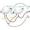
The diagram attached is where my brain registered where the resistor are incorrectly placed on the base. There are also numerous circuits where they are attached to the collector. This diagram and others must be totally wrong.

The reason I wanted to keep the heat sinks separate was to get the largest heat sinks I could using a fan. If a fan is blown along a finned heat sink with the transistors in a row then the one furthest from the fan gets hottest. Even if the fan is placed above then there will less of a variation in temperature. If they are on a single heat sink then those at the ends will be colder. I thought that having a high air flow with 4 heat sinks in a star pattern end on equally in a high air stream from above would give the most even cooling.

I have done some work on oil coolers in the past. Strange that 'heat flow' should rear it's ugly head again.

I had read that it was best to buy all the transistors at the same time so that hopefully they would have similar characteristics. I did.

I have assumed this resistor is being used as a current limiter by getting hot and changing it's resistance ? I can understand why a small change in Vbe makes such a difference but there are so many variables to upset this heat runaway safeguard it does concern me. I suppose all you can do is limit the variables as much as you can.

On those videos I sent a link to it appears that regardless of the case temperature the heat sink temperature varied much less, even right behind the transistor case with only a 2C to 4C change to the edge of a large heat sink.

I had hoped that running these 2N3055's at a quarter of their rating (30W) and running them as cool as practical might cause less problems. I estimate that the case temperature will be below 36C based on the experiments in those videos. He did not try with a high air flow metal to metal with heat compound so I had to extrapolate. I suspect though that if one transistor runs away then that low temperature does not matter.

I must be trying your patients Steve. Thank you for being so kind.
I am not as mobile as I was and this hobby is helping a lot. The last thing I built was 50 years ago - a Mullard EL34 20W stereo pair. EF86, ECC83 GZ34 - 410v 0 410V ) 0.5% distortion at 20W. Some things you don't forget. Like when I was underneath it and the 410V rail came undone and hit my nose. I still have the scar. I was touching the chassis.

Thanks again Steve.
 

Attachments

  • 2N3055 in parallel.jpg
    2N3055 in parallel.jpg
    36.3 KB · Views: 96
Top