Maker Pro
Maker Pro

Bridge rectifier melted.

sandtaz

May 19, 2014
38
Joined
May 19, 2014
Messages
38
Hello all. I need some advice. Here is my situation: I have a Whisper 200 wind generator that puts out max 1000 watts at 24 volts AC to help charge my battery bank. The three wires from the generator ran (notice past tense) thru a 60A max bridge rectifier to get it to dc which goes to a Xantrax c60 charge controller/load diversion and then to batteries/dump load. Last week I found the rectifier burnt to a mass of plastic and signs of high heat. Wires into and out of the rectifier were burnt about an inch from the unit but no further. Could the Chinese made rectifier have just failed internally and caused the melt down? My first thought was to just replace the rectifier and see what happens but then decided to get advice from knowledgeable people like you guts. Thanks for any input to an electronically challenged individual.
 

BobK

Jan 5, 2010
7,682
Joined
Jan 5, 2010
Messages
7,682
I'd look for a short at the output of the rectifier before replacing it.

What kind of a heat sink are you using? At 60A a bridge rectifier dropping about 1.4V will dissipate 84 Watts.

Bob
 

(*steve*)

¡sǝpodᴉʇuɐ ǝɥʇ ɹɐǝɥd
Moderator
Jan 21, 2010
25,510
Joined
Jan 21, 2010
Messages
25,510
Yeah, my guess is a lack of heatsinking.

Typical failure of a diode (or diodes within a diode bridge) is to short circuit. Assuming power doesn't flow back from the charger this will tend to cause dynamic braking of the generator with the heat generated (mostly) in the generator.

edit: If you go beyond this (especially if you feed power back from something like a lead acid battery) the device may ultimately fail open circuit, but this is typically more mechanical (the device fractures) than thermal (melted) in appearance.
 
Last edited:

Colin Mitchell

Aug 31, 2014
1,416
Joined
Aug 31, 2014
Messages
1,416
I would put one bridge on top of another.
The voltage will not be 1.4v but 1.1v plus 1.1v = 2v2 at 60A = 132 watts!!!!
 

Harald Kapp

Moderator
Moderator
Nov 17, 2011
13,722
Joined
Nov 17, 2011
Messages
13,722
I would put one bridge on top of another.
Does that mean to connect them in parallel?

The voltage will not be 1.4v but 1.1v plus 1.1v = 2v2 at 60A = 132 watts!!!!
How do you arrive at these numbers?
I assume with 'not be 1.4v but 1.1v plus 1.1v' you refer to the voltage drop across each diode pair of the rectifier being smaller due to less current. A valid assumption. Exact values may vary, however. From there on it is either:
  • 1.1V*60A=66W or
  • 2.2V*30A=66W
The error is in doubling the voltage while keeping the currrent the same. You either double the voltage but halve the current to account for the 1:1 distribution of currents between the two recifiers. Or you use the reduced voltage of the diode pair and full current.
A simple plausibility check: When the voltage drop is lower than with a single rectifier, the power dissipated cannot be higher, cf. post #2 by Bob.

Anyway: a heat sink will still be required.
 

Colin Mitchell

Aug 31, 2014
1,416
Joined
Aug 31, 2014
Messages
1,416
You are wrong with your knowledge.

At 60 amp the voltage across each diode will be about 1.1v NOT 0.7v.
 

Harald Kapp

Moderator
Moderator
Nov 17, 2011
13,722
Joined
Nov 17, 2011
Messages
13,722
At 60 amp the voltage across each diode will be about 1.1v NOT 0.7v.
You may or may not have a point here, depending on the characteristics of the rectifier used.

A real reduction in power dissipation can be achieved with a so called ideal diode.
 

shrtrnd

Jan 15, 2010
3,876
Joined
Jan 15, 2010
Messages
3,876
Easy boys.
We've already got one user with burning bridges.
We don't want to be burning any more of them between ourselves.
I vote for the inappropriate heat sink.
 

sandtaz

May 19, 2014
38
Joined
May 19, 2014
Messages
38
Yeah, my guess is a lack of heatsinking.

Typical failure of a diode (or diodes within a diode bridge) is to short circuit. Assuming power doesn't flow back from the charger this will tend to cause dynamic braking of the generator with the heat generated (mostly) in the generator.

edit: If you go beyond this (especially if you feed power back from something like a lead acid battery) the device may ultimately fail open circuit, but this is typically more mechanical (the device fractures) than thermal (melted) in appearance.
Bob, Steve and all: thanks for the replies. As I remember, there was a thin heat sink on the back of the rectifier. There is not enough left to determine the size of the heat sink. It was attached inside a steel enclosure. I have the original failed pc board with two heat sinks attached. There are approx 1x1x6" each. I could use these as the heat sink for a new rectifier. Do you think this would be an appropriate size for a heat sink? Based on the numbers I included in first post (1000w max at 24v AC) what size rectifier would you suggest? Sure miss the wind generator. I have had to run the backup diesel gen several times since the thing burnt up. Thanks to everyone for their help.
 

BobK

Jan 5, 2010
7,682
Joined
Jan 5, 2010
Messages
7,682
Sizing a heatsink is a complicated calculation.

You have to know:

1. The max operating temp of the diodes
2. The thermal resistance of junction to case
3. The max air temp at which it will operate
4. The thermal resistance from case to heatsink (depends on how it is mounted)

Then you can calculate the thermal resistance of heatsink to air that you need.

The "small heatsink" on the bridge was actually probably a mounting tab for a larger heat sink.

Bob
 

sandtaz

May 19, 2014
38
Joined
May 19, 2014
Messages
38
Sizing a heatsink is a complicated calculation.

You have to know:

1. The max operating temp of the diodes
2. The thermal resistance of junction to case
3. The max air temp at which it will operate
4. The thermal resistance from case to heatsink (depends on how it is mounted)

Then you can calculate the thermal resistance of heatsink to air that you need.

The "small heatsink" on the bridge was actually probably a mounting tab for a larger heat sink.

Bob
Thanks Bob, but I cannot do this calculation. I appreciate you taking your time.
 

Colin Mitchell

Aug 31, 2014
1,416
Joined
Aug 31, 2014
Messages
1,416
All this discussion misses out the most important factor:

Sizing a heatsink is a complicated calculation.

You have to know:

1. The max operating temp of the diodes
2. The thermal resistance of junction to case
3. The max air temp at which it will operate
4. The thermal resistance from case to heatsink (depends on how it is mounted)

Then you can calculate the thermal resistance of heatsink to air that you need.


The voltage across a diode increases considerably as the current rises.
You do not know this value and it adds 50% or more to all the calculations you are making.
All the calculations above are absolutely worthless and I am surprised (no I'm NOT) that no-one has even started to mention this fact. That's because no-one has actually serviced the problem.
It's like a Priest talking about sex.
 

sandtaz

May 19, 2014
38
Joined
May 19, 2014
Messages
38
All this discussion misses out the most important factor:

Sizing a heatsink is a complicated calculation.

You have to know:

1. The max operating temp of the diodes
2. The thermal resistance of junction to case
3. The max air temp at which it will operate
4. The thermal resistance from case to heatsink (depends on how it is mounted)

Then you can calculate the thermal resistance of heatsink to air that you need.


The voltage across a diode increases considerably as the current rises.
You do not know this value and it adds 50% or more to all the calculations you are making.
All the calculations above are absolutely worthless and I am surprised (no I'm NOT) that no-one has even started to mention this fact. That's because no-one has actually serviced the problem.
It's like a Priest talking about sex.
Colin, thank you for your input. So, what size heat sink do I use?
 

(*steve*)

¡sǝpodᴉʇuɐ ǝɥʇ ɹɐǝɥd
Moderator
Jan 21, 2010
25,510
Joined
Jan 21, 2010
Messages
25,510
Colin, I'm not arguing that there's likely to be 2v or more across the bridge at full load.

However your abrasive attitude is not conducive to getting people to agree with you.

The main problem here appears to be a total lack of heatsinking rather than inadequate heatsinking due to a miscalculation of dissipated heat.

I suggest that if the OP listens to @BobK then we'll be looking for a datasheet to get us some of the missing data and that will include the forward voltage drop.

At this point we have a reasonable idea of the rating of the alternator, but know little about the typical and max load.

Assuming that the turbine is governed in some way, the current at max power is likely to be about 42A RMS. Even at 2.5 V drop, you're not looking at 130W.
 

Colin Mitchell

Aug 31, 2014
1,416
Joined
Aug 31, 2014
Messages
1,416
The only way to set up a heatsink is to load the output with car lamps and add a heat-sink. If you can keep your fingers on the heat-sink for 10 minutes, it is large enough.
 

sandtaz

May 19, 2014
38
Joined
May 19, 2014
Messages
38
Colin, I'm not arguing that there's likely to be 2v or more across the bridge at full load.

However your abrasive attitude is not conducive to getting people to agree with you.

The main problem here appears to be a total lack of heatsinking rather than inadequate heatsinking due to a miscalculation of dissipated heat.

I suggest that if the OP listens to @BobK then we'll be looking for a datasheet to get us some of the missing data and that will include the forward voltage drop.

At this point we have a reasonable idea of the rating of the alternator, but know little about the typical and max load.

Assuming that the turbine is governed in some way, the current at max power is likely to be about 42A RMS. Even at 2.5 V drop, you're not looking at 130W.
According to the literature that came with the turbine, it is governed by speed of the propeller not output. Manufacturer is out of business or I would be asking these question to them. The literature is not very technical in nature so limited data is available. Remember that power is sent to a 60A DC charge controller that transfers power to a dump load after batteries have reached a fully charged state (approx 31 volts). Turbine is always under load. I wish that I could provide more info but I do not know what to add. From what I have read here, the 60A rectifier would have worked just fine with a proper heat sink. I really appreciate all the time that all here have given my question.
 

(*steve*)

¡sǝpodᴉʇuɐ ǝɥʇ ɹɐǝɥd
Moderator
Jan 21, 2010
25,510
Joined
Jan 21, 2010
Messages
25,510
The only way to set up a heatsink is to load the output with car lamps and add a heat-sink. If you can keep your fingers on the heat-sink for 10 minutes, it is large enough.

The only way? Glad to know that's how real engineers do it Colin.
 

(*steve*)

¡sǝpodᴉʇuɐ ǝɥʇ ɹɐǝɥd
Moderator
Jan 21, 2010
25,510
Joined
Jan 21, 2010
Messages
25,510
From what I have read here, the 60A rectifier would have worked just fine with a proper heat sink.

The diode junctions probably have an absolute max temperature of 150C. Let's assume an ambient temperature of 40C. This means the junction can rise 110C above ambient.

Let's also assume the regulator needs to dissipate 80W of heat. This means that for every watt of heat the temperature can rise by no more than 110/80 degrees. This is 1.375 degrees C per watt.

Now we need to look at how we can make all the thermal resistances add up to less than 1.375 degC/W.

First is the thermal resistance from the junction to the case of the rectifier.

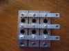
Here is a 50A bridge, and here is the datasheet.

The typical forward voltage drop at 40A is a shade over 1V. Note that this is at 20degC, as the temperature rises this voltage will fall (which will reduce dissipation -- a good thing)

Note the thermal resistance junction to case is 2 deg C/W. This part would not be suitable.

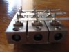
Let's try a "beefier" bridge. Here is one, and here is the datasheet.

The first thing to notice that at 25C the device can dissipate 140W. This doesn't mean that it can do this without a heatsink, it simply means that if you keep the case at 25C the device can safely dissipate 110W. This is actually a fairly fine margin.

The thermal resistance from the junction to the case is 1.15 degC/W, and the typical resistance to the heatsink is a further 0.1 degC/W. This eats up 1.25 degC/W of our 1.375degC/W budget.

You would have to find a heatsink rated at 0.125degC/W. This would be *huge*

However, we can do better. Imagine we could use the diode bridge we looked at first, but at half the current.

Now it dissipates 40W and or allowance becomes 110/40 or 2.75 degC/W. Allow another 0.1 degC/W for the connection to the heatsink and we now have 0.65degC/W remaining.

How does this help? Well, if we place two of these rectifiers in parallel, we can get by with smaller heatsinks. However, for this to work we need them both to be mounted to the same heatsink! At what does it's thermal resistance need to be? Easy, 0.65/2 degC/W. So you want a heatsink rated at about 0.3degC/W

This is still a massive heatsink, but it is probably a third of the size of a 0.125degC/W heatsink.

Can we do better? Sure. If there is a marge enough piece of metal that we can connect the rectifiers to, one that remains at about ambient temperature, we can use this to simply conduct the heat away. We can also use a fan to pass air over the heatsink (does the original case have a fan in it?) or we can even water cool the heatsink.

We can also assume that at higher wind speeds the ambient temperature will be lower, and that the same wind will more effectively cool the heatsink. We can also assume that it won't be operating at full power for very long. All of these things allow us to reduce the size of the heatsink.
 

sandtaz

May 19, 2014
38
Joined
May 19, 2014
Messages
38
Thanks to everyone who helped this electronically challenged individual solve the problem of bridge rectifier melting. I took the suggestion and purchased a 65A rectifier with a heat sink attached. Installed it yesterday and all seems fine. During my wait for the new rectifier, I went thru the parts and pieces for the old charge controller that came with the wind generator and found what looks like a bridge rectifier. If it is, then it looks like a substantial one. The three lugs on the bottom are connecting points for the three wires coming from the gen. The three "tabs" on top were connected to the printed circuit board with the upper most "tab" connected only for support. There is no apparent connection from this mounting point to the rest of the board. I held the board up to strong light and could not see any connection. If I am correct, this would make this a three AC wire in and
a two DC wire out. Does this make sense? Tried testing each of the nine diodes with my digital MM but did not get any results. Would it be better to test with an analog meter? Any ideas will be greatly appreciated. Tom.
 

Attachments

  • IMG_7857.JPG
    IMG_7857.JPG
    149.3 KB · Views: 88
  • IMG_7858.JPG
    IMG_7858.JPG
    122.8 KB · Views: 81

(*steve*)

¡sǝpodᴉʇuɐ ǝɥʇ ɹɐǝɥd
Moderator
Jan 21, 2010
25,510
Joined
Jan 21, 2010
Messages
25,510
It's hard to tell. Perhaps the original design was for a three phase delta wound generator?
 
Top